With multi driver sub systems which often feature dual voice coils dvc on each driver the level of wiring complexity can be enough to turn off even the most adventurous of car audio do it yourselfers. Fear not though for we have compiled wiring diagrams of several configurations for dual voice coil dvc drivers.
How To Wire A Dual Voice Coil Speaker Subwoofer Wiring Diagrams
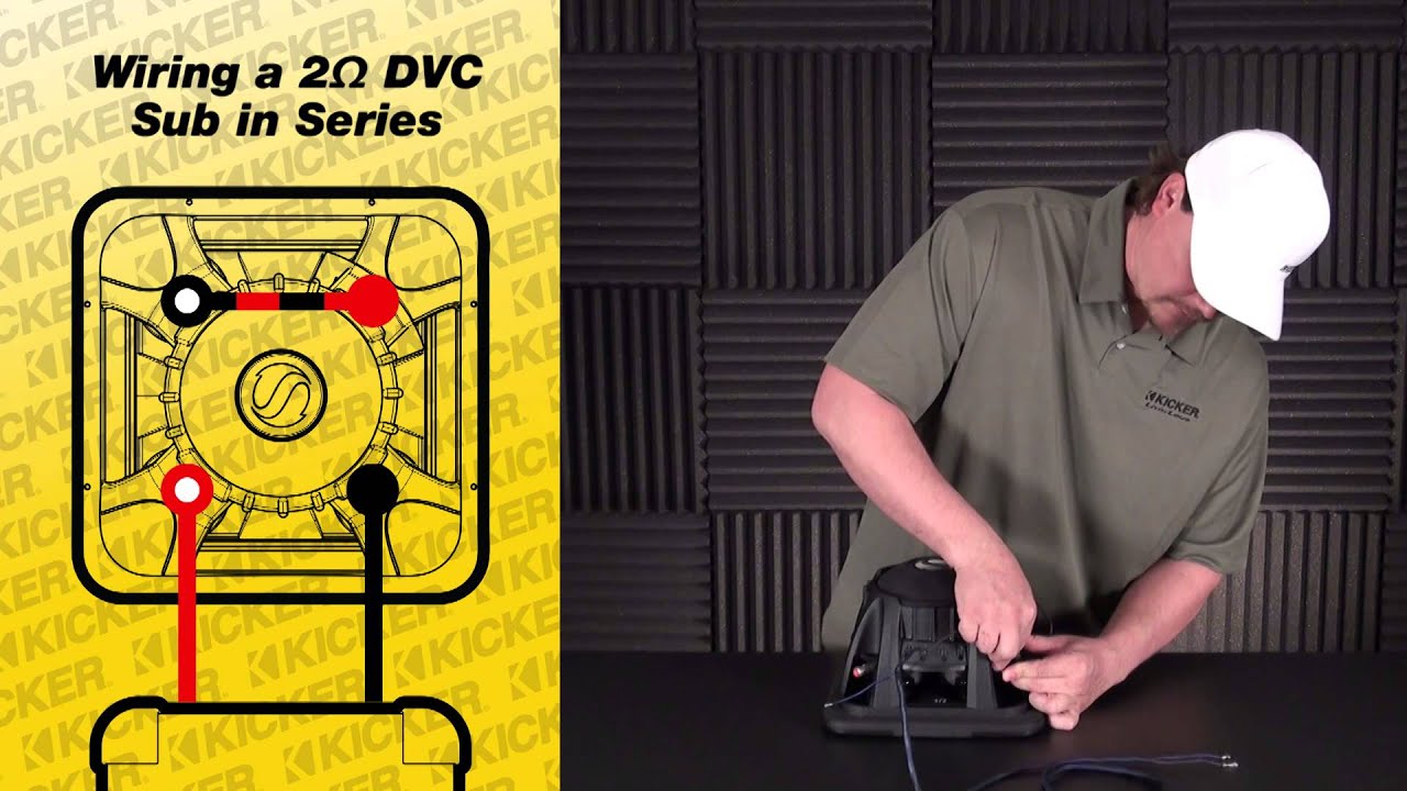
Dvc subwoofer wiring diagram. 4 ohm mono is equivalent to 2 ohm. If yours is a dvc 4 ohm sub wire it like this diagram. The following diagrams are the most popular wiring configurations when using dual voice coil woofers. Select the impedance that your subwoofers are rated for. Your ad blocker is preventing this page from displaying correctly. Dual voice coil wiring options.
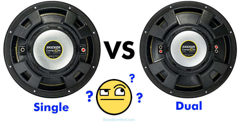
I have 2 dd 600 series dvc 4ohm trying to get them to 1 ohm with a 2 channel amp how do i do that. They show a typical single channel wiring scheme. Check the amplifiers owners manual for minimum impedance the amplifier will handle before hooking up the speakers. If your sub is a dvc 2 ohm sub then youd wire it like this. A svc speaker has one voice coil and one set of terminals one positive and one negative. Both subwoofers need to have the same voice coil configuration.
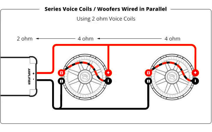
Because of this dvc speakers typically subwoofers offer. This subwoofer wiring application includes diagrams for single voice coil svc and dual voice coil dvc speakers. Thaddeus turner from kingsland. A dvc speaker has two voice coils each with its own set of terminals. Two 2 ohm dual voice coil dvc speakers wiring diagrams. For example if it says it is a dual voice coil dvc subwoofer and you want to run two subwoofers they both need to be dvc woofers.
The location of positive and negative speaker terminals have been reversed in one or more diagrams for easier readability. For example if the woofer says single 4 ohm voice coil you would. Dvc subwoofer wiring diagram wiring diagram is a simplified gratifying pictorial representation of an electrical circuitit shows the components of the circuit as simplified shapes and the power and signal contacts surrounded by the devices.
Gallery of Dvc Subwoofer Wiring Diagram