The regulator is available in two versions called dsr and dsra the first is the standard one optimized for mecc alte. To maximize performance the regulator should be understood as part of a system made up of at least three components.
Mecc Alte Dsr Avr Voltage Regulator General Power
Dsr avr wiring diagram. Mecc alte ecp series is 1 or 3 phase brushless rpm avr controlled phase avr controlled with aux winding 6 or 12 wire rpm brushless units. Applicable standards and guides 3. Because the dsr is a digital version the parameters can be adjusted via. The avr also incorporates an interface to the optional excitation boost system ebs for use where short circuit current maintenance is required. With our digital avr regulator it is possible to control and adjust the range of voltage electrically through our compatibility software. Generator no load 36.
Collection of sx460 avr wiring diagram. Generator full load 35. Initial excitation circuit 33. Automotive voltage regulator wiring diagram collections of 1951 chevy voltage regulator wiring diagram chevy trusted wiring. Excitation and automatic voltage regulator system 12 table of contents 1. To maximize performance the regulator should be understood as part of a system made up of at least three components.
The engine is a lister petter ac1 series ii and the alternator is a markon sc21g. Wiring diagram for voltage regulator best wiring diagram alternator. The avr voltage sensing. Alarm and signaling panel 38. To maximize performance the regulator should be understood as part of a system made up of at least three components. Automotive voltage regulator wiring diagram download.
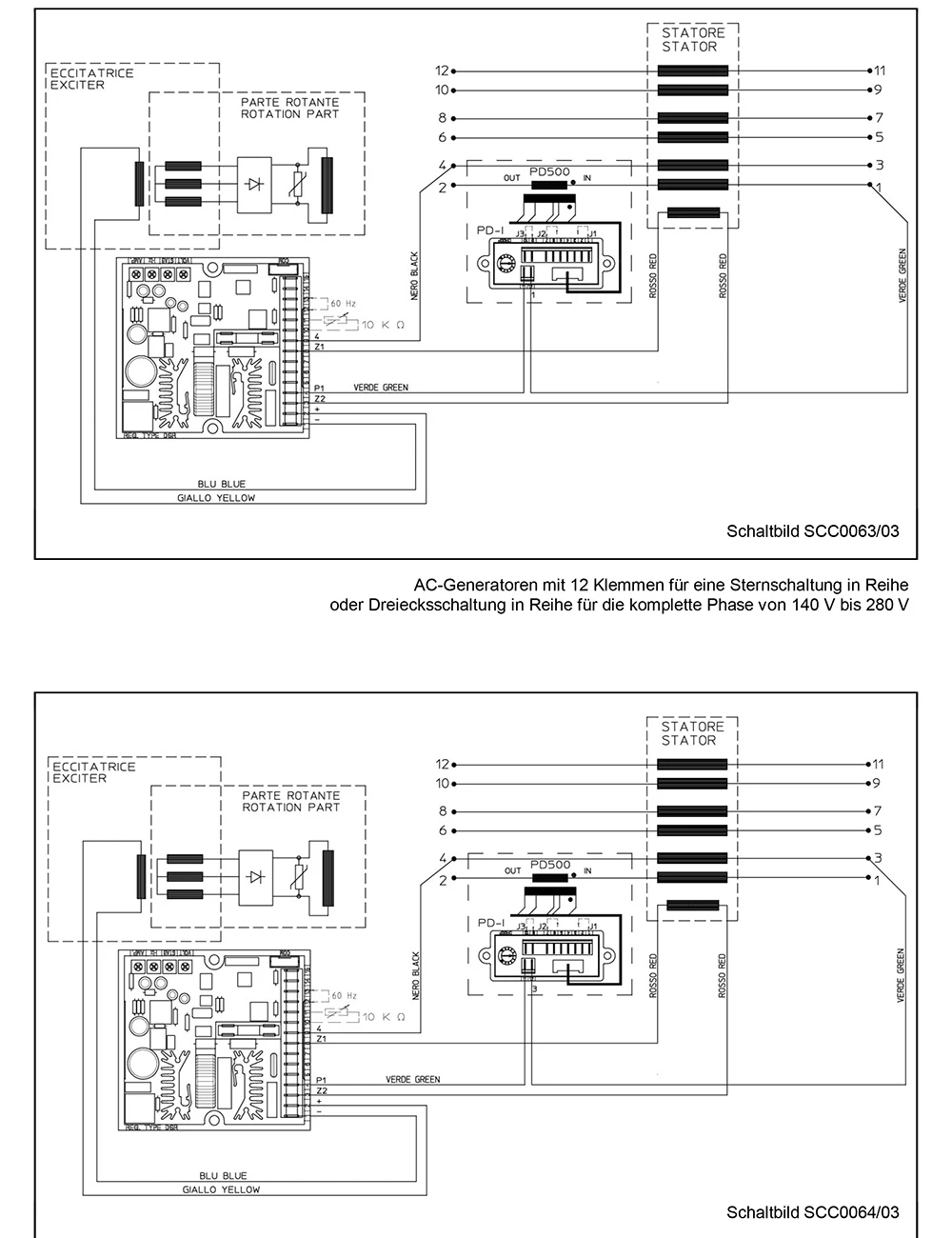
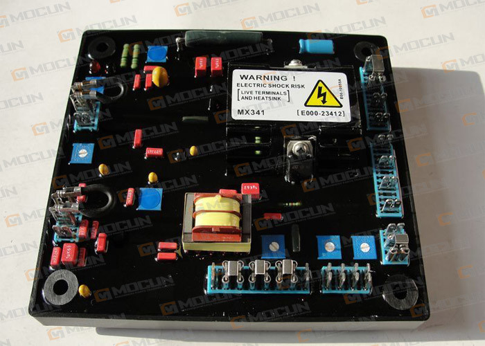
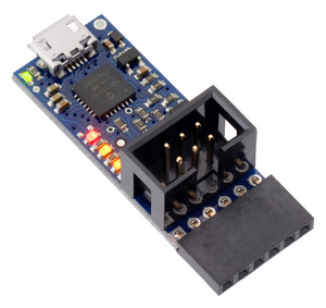
The voltage can be regulated by the volt potentiometer on the avr regulator or by an external control device commonly used by the genset industry to govern the genset. The dsr control unit a communications module usb2dxr for example and a su. Retro fitting an automatic voltage regulator to a 1997 diesel generator. The dsr is a voltage regulator for synchronous alternators designed for stand alone working and calibra tion. The dsr is a voltage regulator for synchronous alternators designed for stand alone working and calibra tion. Eco ecp manual september revision 2.
The avr is linked with the main stator windings and the exciter field windings to provide closed loop control of the output voltage with load regulation of 10. The dsr control unit a communications module di1 for example and a supervision unit. The set was built by warsop power tools. Wiring diagram alternator voltage regulator fresh 4 wire alternator. Objective and field of application 2. It reveals the elements of the circuit as streamlined forms as well as the power and signal connections in between the tools.
The dsr control unit a communications module di1 for example and a supervision. A wiring diagram is a streamlined standard photographic depiction of an electric circuit. Mecc alte dsr is a voltage regulator for synchronous alternators designed for standalone working and calibration.
Gallery of Dsr Avr Wiring Diagram