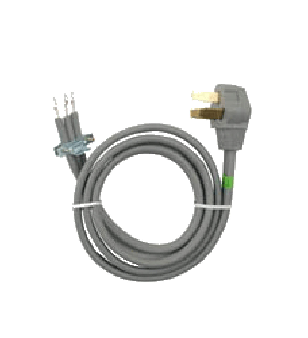
Two hot wires and the third contained both ground and a neutral wire. The ground is now a dedicated wire also.

Wiring Diagram For Dryer F7 Wiring Diagram
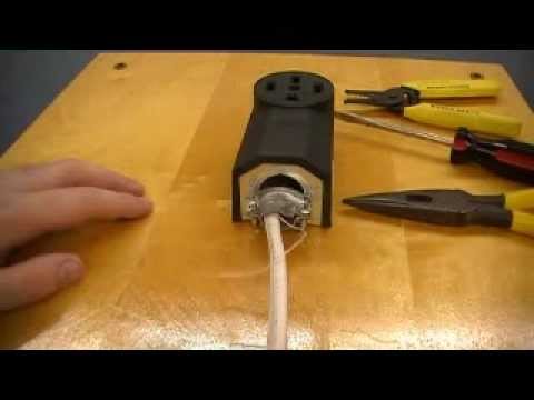
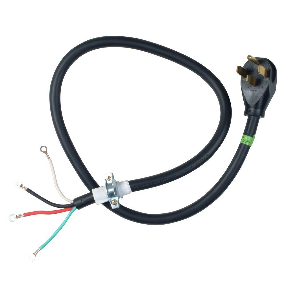
Dryer receptacle wiring diagram. This system worked pretty well and is still in use in many homes today but there is more potential for electrical. As you can see there is now an added dedicated neutral. But if you notice both the neutral and the ground wires both connect to the same ground bar inside the panel box. This article will explain what options you have to get your dryer wired and running. The long slot on the left is the neutral contact and the short slot is the hot contact. Electrical wiring for a dryer power cord has a typical 240 volt electric power cord with 3 wire and 4 wire wiring configurationsmany people may experience the situation of trying to make a older dryer work with an new four wire receptacle.
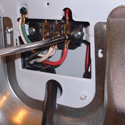
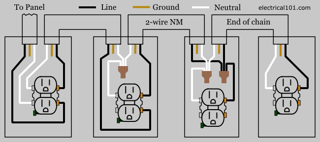
The black wire line a phase and the red wire line b phase supply the 240 volts. In the to the right a 3 wire 10 awg nm cable supplies 240 volts from the electrical panel to the dryer receptacle outlet box. This is a standard 15 amp 120 volt wall receptacle outlet wiring diagram. The white wire supplies neutral to the dryer receptacle. Dont use this receptacle when no ground wire is available. The ground connection is shown in this diagram.
This is a polarized device. A grounded contact at the bottom center is crescent shaped. 4 prong dryer receptacle wiring diagram wiring diagram is a simplified pleasing pictorial representation of an electrical circuit. Before 1996 electric dryers were supplied by a dedicated circuit that had three conductors. It shows the components of the circuit as simplified shapes and the capability and signal friends amongst the devices. The 4 prong dryer outlet wiring diagram above is ran with a 103 with ground cable.
As mentioned earlier the neutral and ground are. Wiring a grounded duplex receptacle outlet. There was no dedicated ground slot on the receptacle outlet and dryer cords had no ground wire or ground prong.
Gallery of Dryer Receptacle Wiring Diagram