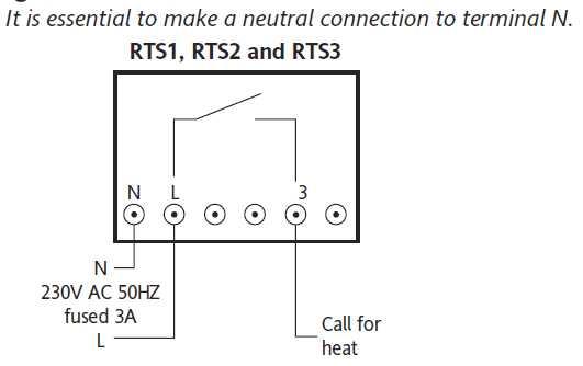
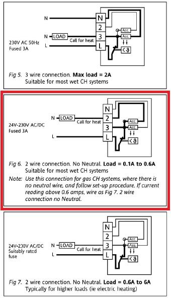
It is essential to make a neutral connection to terminal n. The wiring conversion.
77ecb Wiring Diagram For Central Heating Room Thermos
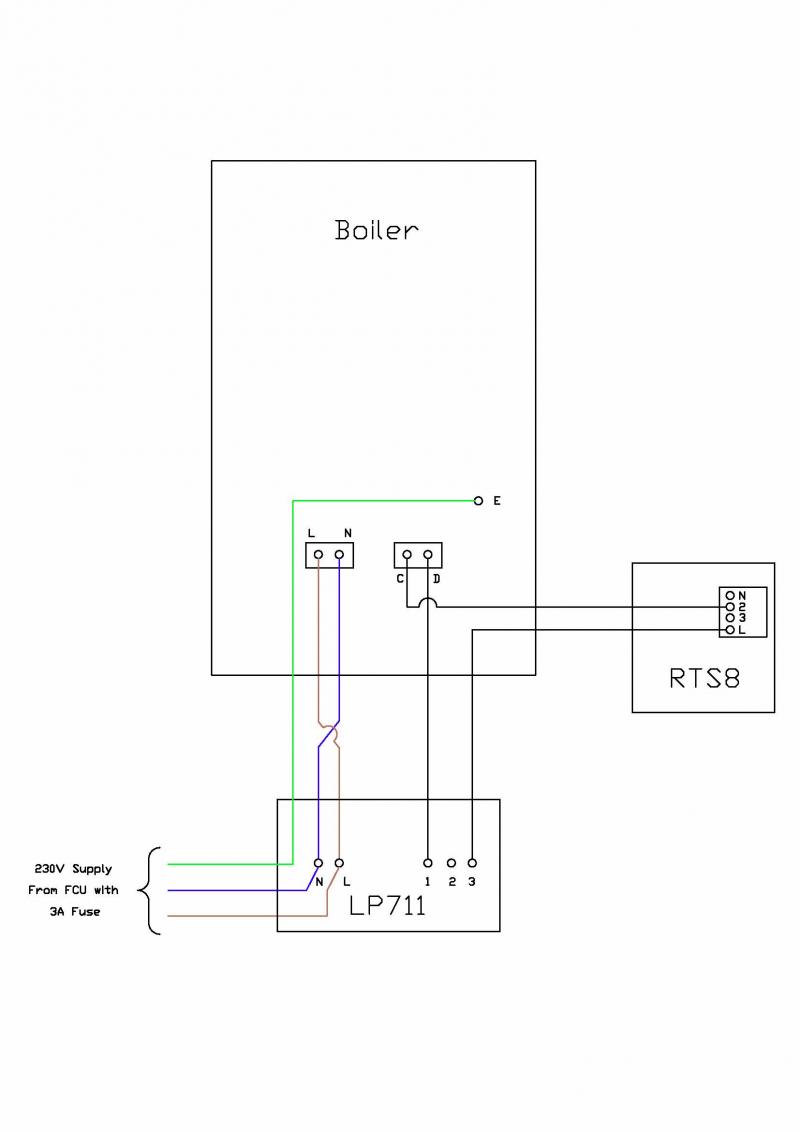
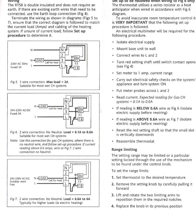
Drayton rts8 wiring diagram. Connections in boiler from timer l n e black to c black to d. Any help greatly appreciated from a first timer on the site. Here you can find useful information training modules and wiring diagrams to help with your day to day job. Information the rts room thermostat replaces earlier models of both acl and drayton room thermostats subject to a maximum load of 21a 230v ac. Fused spur has l n e going to timer. Terminate the wiring as shown in diagrams figs 5 to 7 ensure that the correct diagram is followed to match the current load amps and cabling of the heating system.
Designed for fixed wiring only to comply with current iet wiring regulations bs7671. Related manuals for drayton combi stat rts8. Programmable room thermostat wireless 2. It acl and drayton room thermostats subject to a maximum. Thermostat drayton combi stat rts8 installation instructions and instructions for use 2 pages thermostat drayton rf701 installation instructions. Link between terminals l and 1 if mains voltage is required on the thermostat switch.
Wiring the rts8 is double insulated and does not require an earth if there are existing earth wires that need to be connected use the earth loop connection fig 4. Training centre resources. Load of 21a v ac. Drayton rts8 combistat installation user guide. I would like to connect a room thermostat drayton rts8 to the timer boiler. Wall plate has 5 core l n e black in 1 black in 3 to boiler.
Drayton rts1 manual online.
Gallery of Drayton Rts8 Wiring Diagram