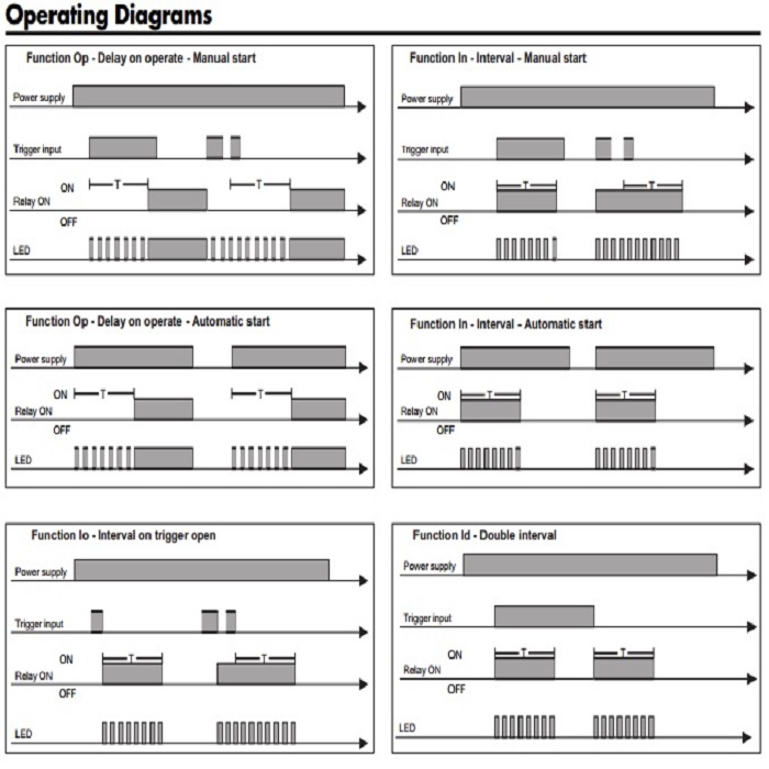
Its possible to wire an addi tional load ie. Fast blinking operating diagrams power supply relay on trigger input t t led.
24 Vdc Wiring Diagram Car And Deep Cycle Battery Frequently
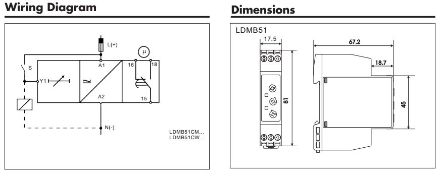
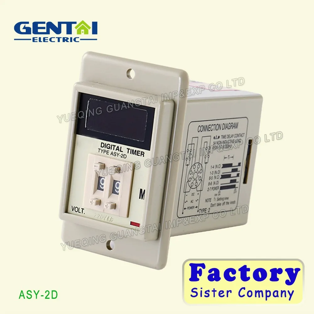
Dmb51cm24 wiring diagram. The dmb51cm24 is a multifunction timer with 7 knob selectable functions and 7 knob selectable time ranges within 01s and 100h. 24 vdc and 24 to 240 vac or 12 to 240 vacdc. Din 175 mm wide suitable both for back and front panel mounting multi voltage range. If the trigger contact is closed before the end of. Its possible to wire an addi tional load ie. Dmb51cm24 summary of contents page 1 automatic or manual start repeatability.
Request carlo gavazzi dmb51cm24. 02 output spdt dpdt relays for mounting on din rail in accordance with dinen 50 022 175 mm dmb51c or 355 mm dmb71d din rail housing din 43880 combined ac and dc power supply led indication for relay status and power supply on. Slow blinking relay on. Switch wiring diagrams a single switch provides switching from one location only. Yellow led working mode timing. Single pole may sound simple but there are different ways to wire a single pole switch.
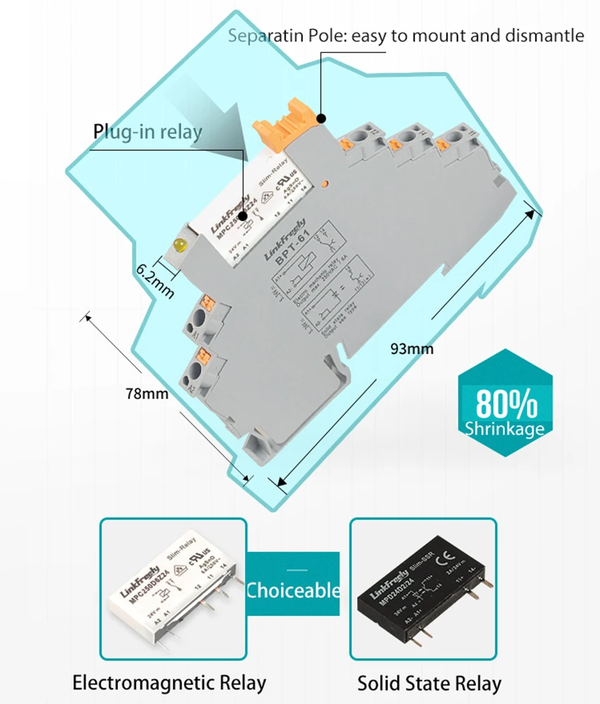
Yellow led working mode timing. Carlo gavazzi multi function timer dmb51cm24 housing. Each of the recommended conversions shows the terminal locations of the old and new devices so the user can plan the conversion appropriately. At the end of the set delay time the relay operates and does not release until the trigger contact is closed again or the power supply is disconnected. Wiring terminal locations moving a wire from the top of the old device to the bottom of the new device in a control panel cannot be taken lightly. Dmb51cm24 series universal timer l compact housing snaps directly to din rail 81x175x672mm h x w x d l timing ranges.
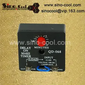
Fast blinking operating diagrams power supply relay on trigger input t t led function op delay on. Time delay relay spdt 100h 240vacdc online from elcodis view and download dmb51cm24 pdf datasheet time delay specifications. See operation diagrams incorrect knobs position. See operation diagrams incorrect knobs position. The time period begins as soon as the trigger contact is closed. The power can come from either the switch box or the fixture box and a set of electrical switch wiring diagrams will explain each of these scenarios to you clearly.
Wiring diagram operation diagrams function aa asymmetrical recycler on first power supply relay on led function ab asymmetrical recycler off first dcb51 general specifications housing dimensions 175 x 81 x 672 mm material pa66 weight approx 100 g screw terminals tightening torque max. A relay between pins y1 and a2 driven by the trigger contact without damaging the device. 05 nm according to iec en 60947 approval ul csa. A relay between pins y1 and a2 driven by the trigger contact without damaging the device. Slow blinking relay on.
Gallery of Dmb51cm24 Wiring Diagram