1771 ife wiring diagram. 1771 ife 1 1756 if16 diff current 1 1492 cm1771 la002 1 1492 conacab005d 1.

Plc 5 20 Analog I O Plcs Net Interactive Q Amp A
1771 ife wiring diagram. Compatibility and data table use is listed below. With an extensive collection of electronic symbols and components its been used among the most completed easy and useful wiring diagram drawing program. The 1771 ife module comes with a 1771 wg wiring arm. The wiring diagram on the opposite hand is particularly beneficial to an outside electrician. 10 12 weeks. The 1771 ife input module belongs in the c series and hence is different from series a or b.
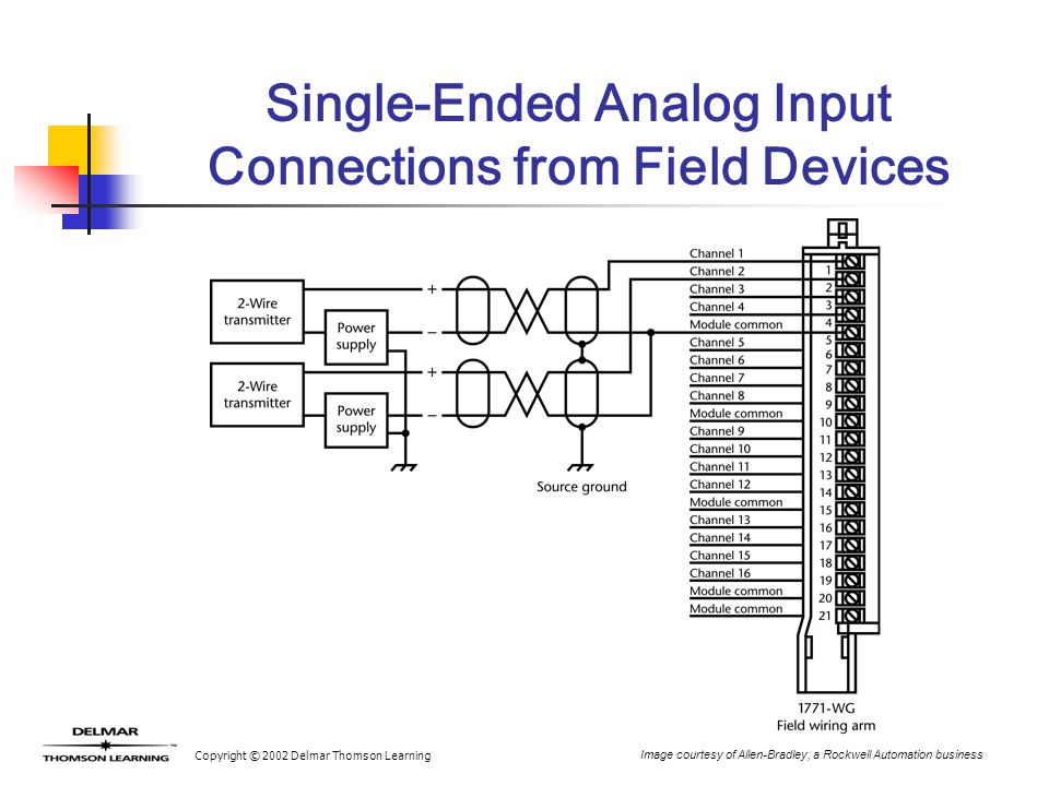
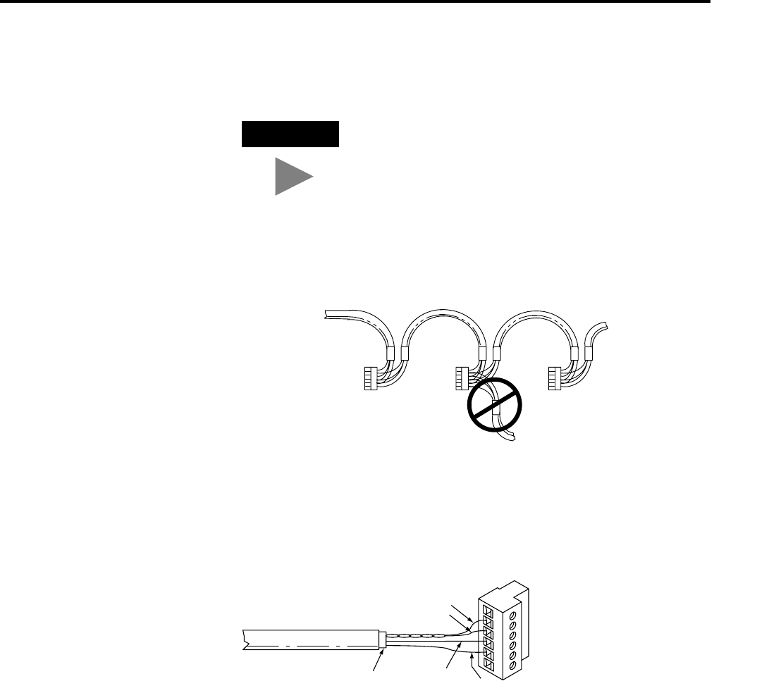
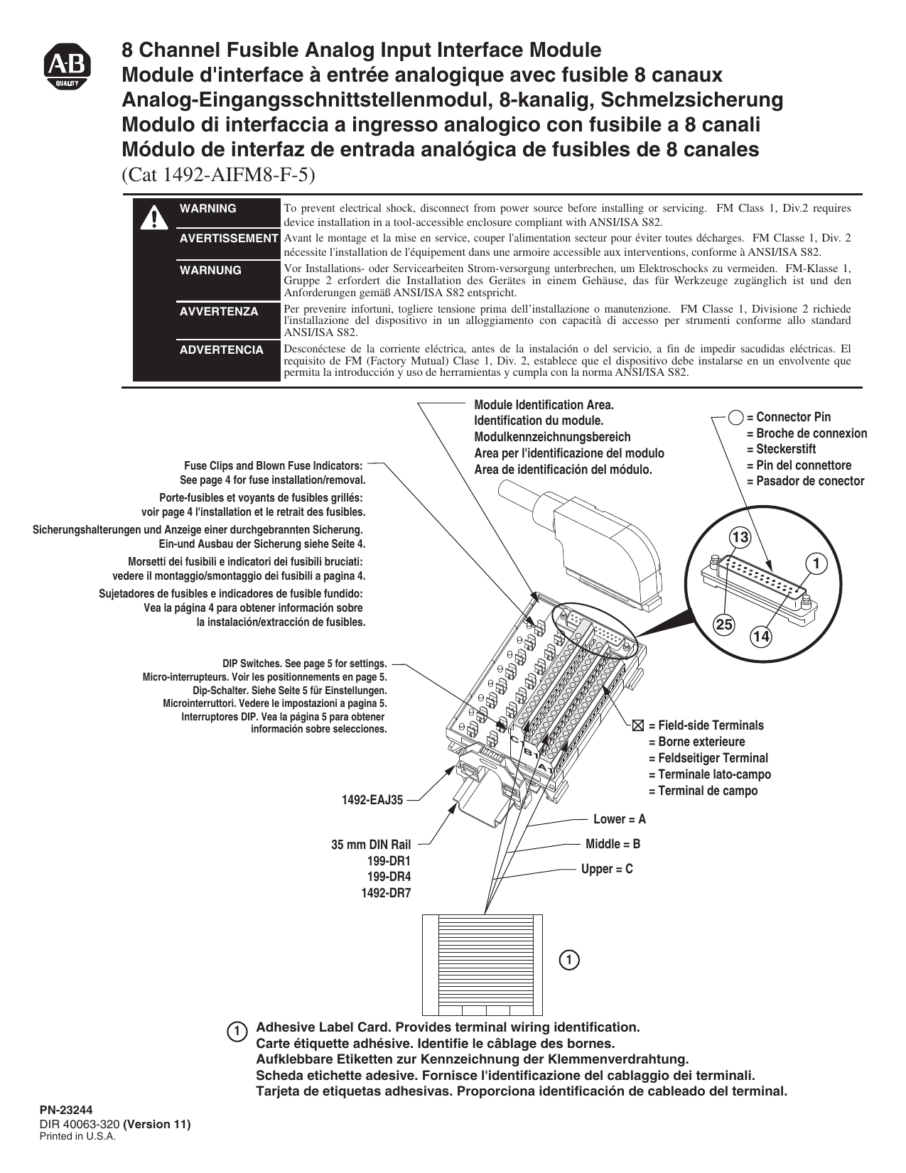
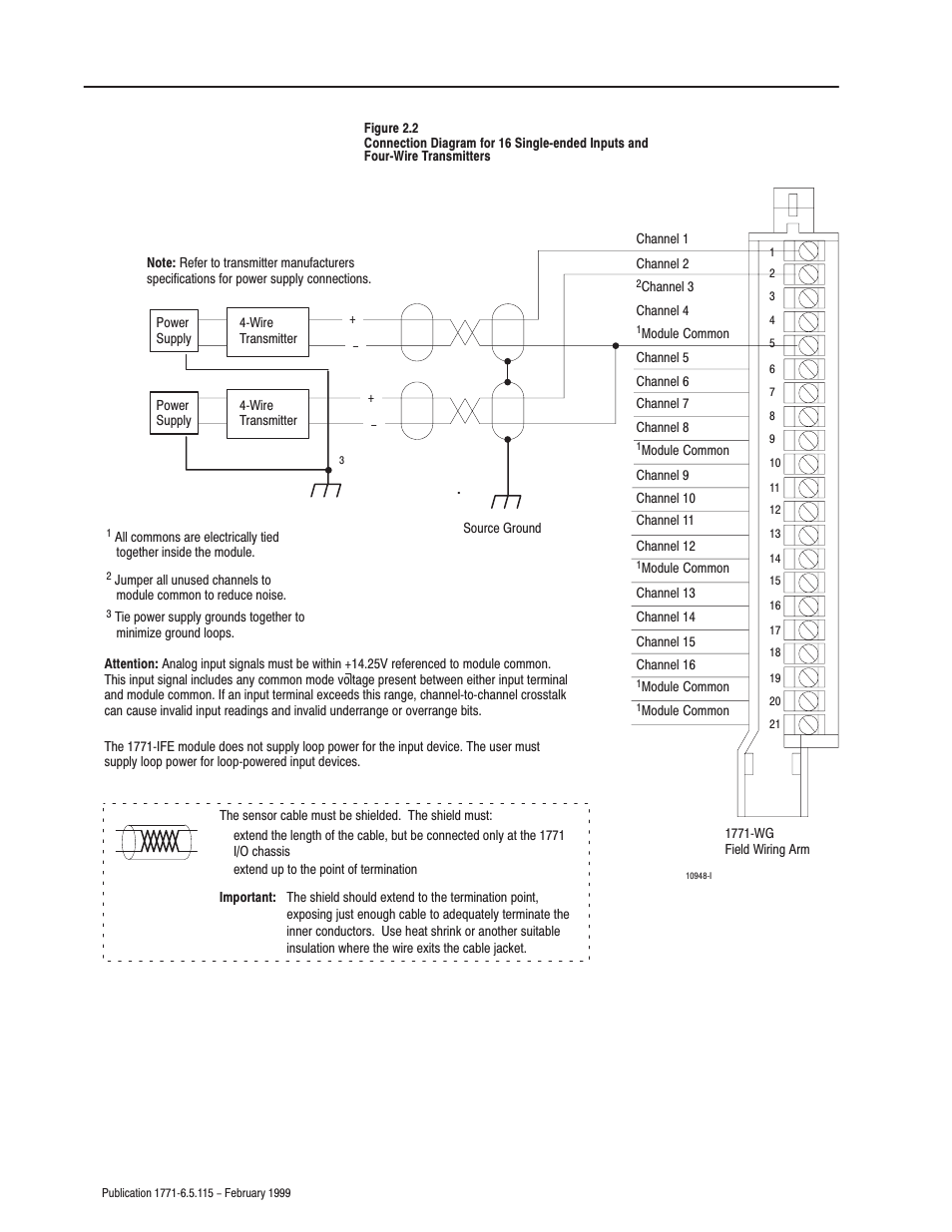
The analog input module is sensitive to electrostatic discharge. 1771 ifea series a rev a. The 1771 ife has a resolution of 12 bit binary and of 12 bits plus sign on the bipolar ranges. C use of data table compatibility catalog number input image output image. Signals should be connected to the screw terminals on the wiring arm as detailed in figure 53 and the wiring arm should be connected to the front tab connector on the 1771 ife. For instance the 1771 ife module has 6 bits or diagnostic information and this represents 6 possible.
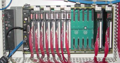
The 1771 ife module comes with a 1771 wg wiring arm. 1771 ife allen bradley analog input module 2005 estimated lead time. Wiring of the field wiring arm 3 module programming sample programs. Industrial automation wiring and grounding guidelines for noise immunity 177041 guidelines for handling lithium batteries ag54 automation systems catalog b111 the 1771 ife module can be used with any 1771 io chassis. For instance the 1771 ife module has 6 bits or diagnostic information and this represents 6 possible. Electrostatic discharge can damage integrated circuits or semiconductors if you touch backplane connector pins.
Communication between the discrete analog module and the processor is. The 1771 ife module can be used with any 1771 io chassis. Revision part also known as. The recommend cable. Connection of analog signals to the 1771 ife is accomplished through the use of the wiring arm. These instructions let the processor obtain input.
Please refer to the manual for more information about the 1771 ife such as the wiring diagrams data sheets firmware information and migration or obsolescence details. Page 1 installation instructions catalog number 1771 ifec use this document as a guide when installing the 1771 ifec analog input module. To understand any issues concerning io module compatibility refer to the conversion module wiring diagrams and the installation manuals for the specific io modules involved with particular attention to the specification and wiring instructions. 1771 ife analog input module wiring connection. The 1771 ife has a resolution of 12 bit binary and of 12 bits plus sign on the bipolar ranges. The 1771 ife input module belongs in the c series and hence is different from series a or b.
Gallery of 1771 Ife Wiring Diagram