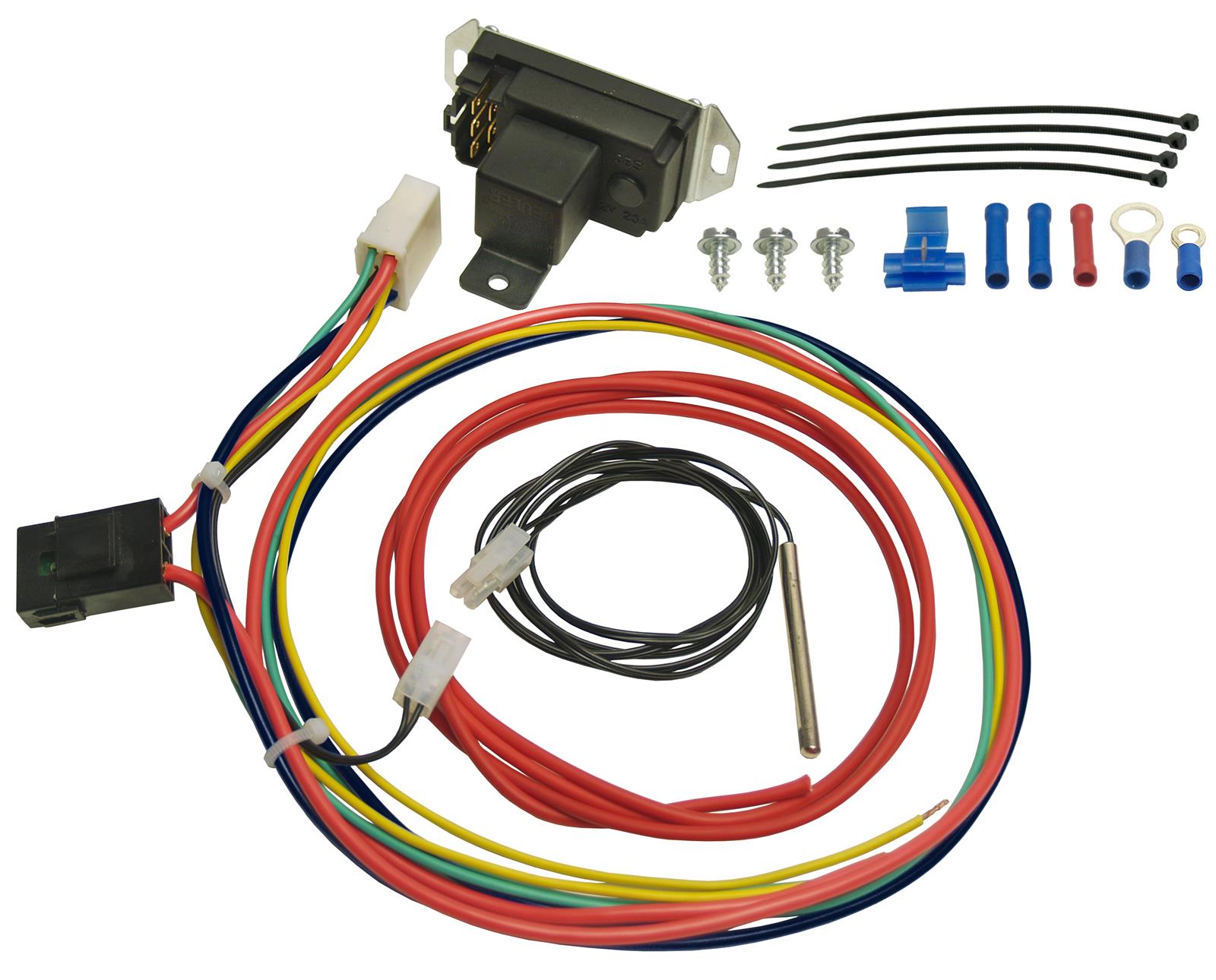
Using a yellow butt connector connect the 10 awg black wire to the negative lead of the fans. View and download derale 16739 installation instructions online.
Compare Derale 25 5 8 Vs Derale 27 Etrailer Com
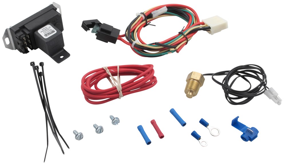
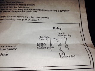
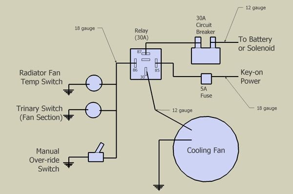
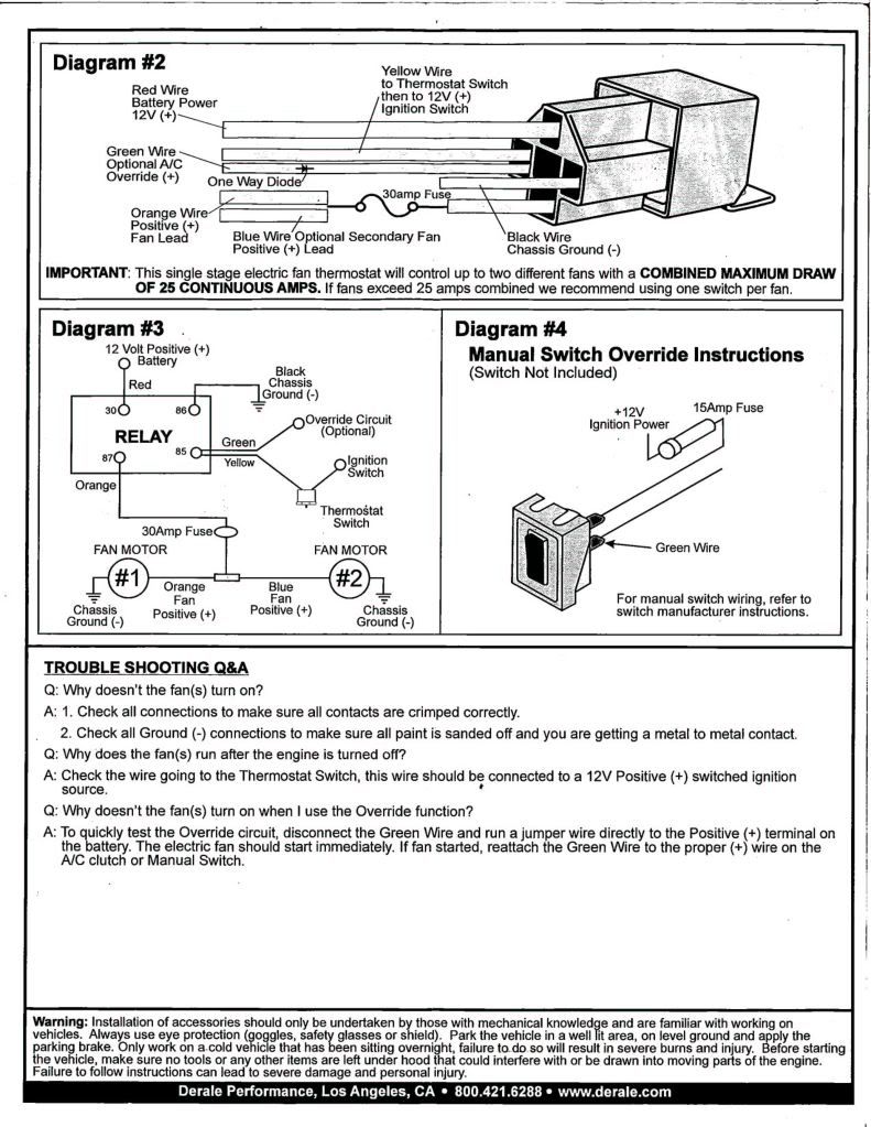
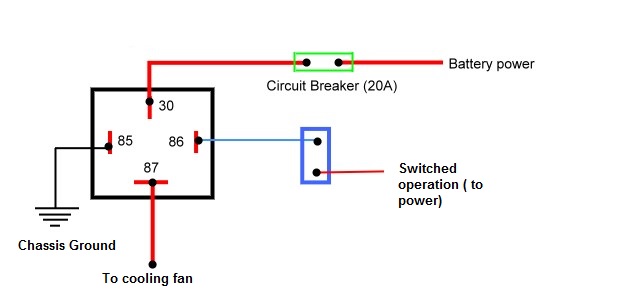
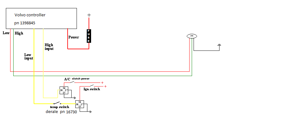
Derale fan wiring diagram. If you choose to operate the fan using both speeds two switching devices or a derale dual fan controller part 16788 or 16789 is recommended. The derale high amperage adjustable dual fan controller is designed to operate two electric fans at different activating temperatures. Override circuit optional the green wire is designed to work in two different configurations. Route the other end of this wire to the fan terminal of the fan controller connect using 8 yellow ring terminal. Description 1 thermostat switch 1 relay wire harness 1 38 npt thread in probe 1 push in probe 1 1 x 1 foam pad 1 retaining clip 4 4 wire ties qty. Fan 1 is designed to activate at the desired adjusted temperature 150 240f.
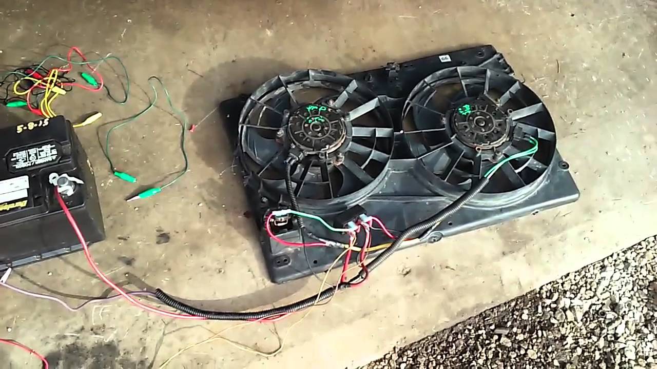
Single stage electric fan. 16739 thermostat pdf manual download. Diagram 2 wiring before starting disconnect the negative cable on the vehicles battery. Reference diagrams 78onpage 2 the electric fan assembly is built using a high output two speed motor.
Gallery of Derale Fan Wiring Diagram