Out load as shown in fig. Construction and working the dc motor is connected with dc power supply and output driver irf 540 mosfet the diode d1 provides protection from back emf the mosfet gate terminal is driven by output signal from pin 5 of lm 3578 pin 8 7 and pin 6 are shorted together and connected with positive supply components c1 c2 and r2.

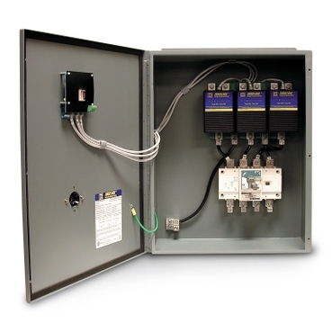
Photovoltaic Spd Pv Spd Surge Protection Device Solar Energy
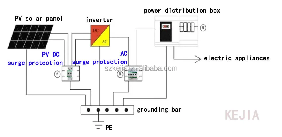
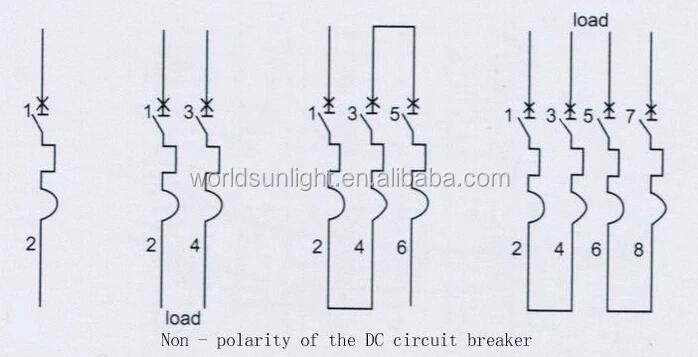
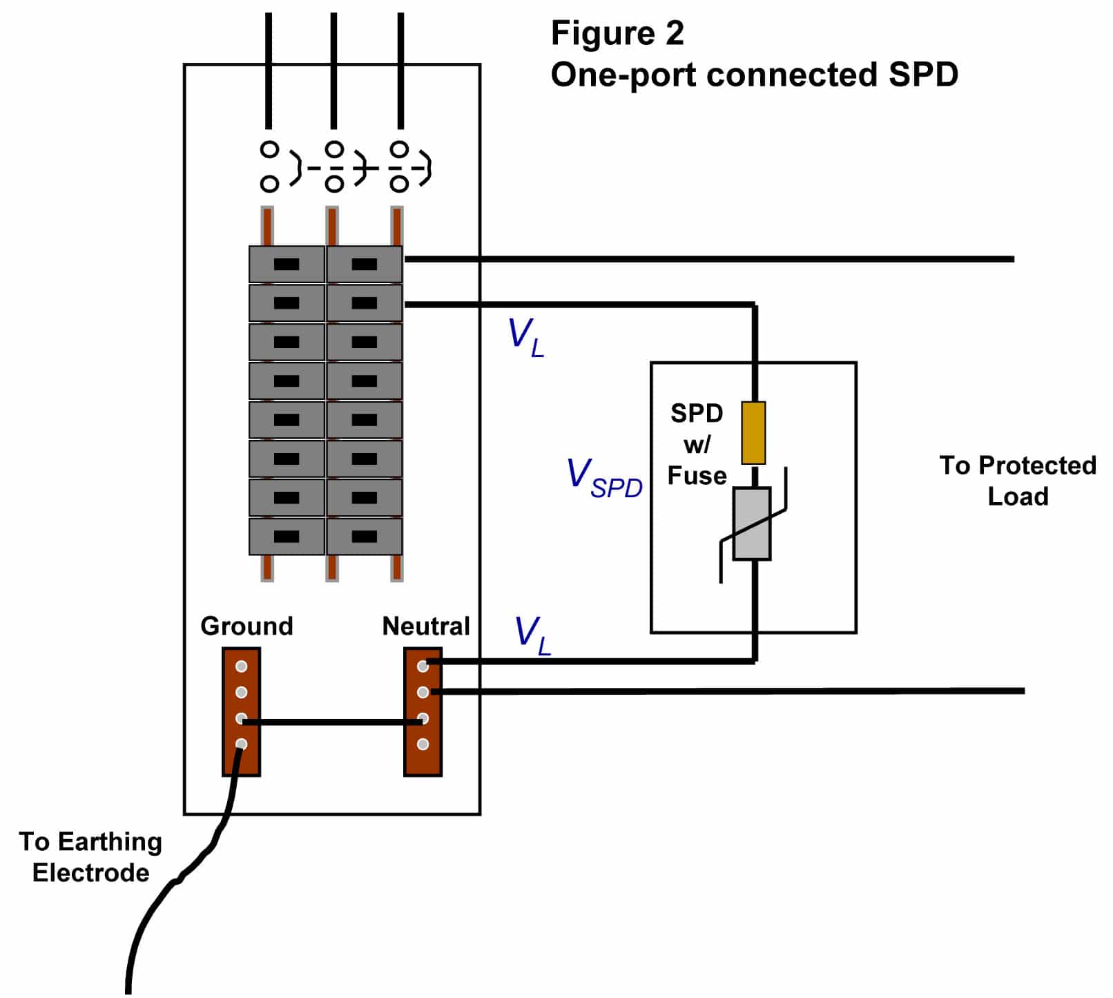
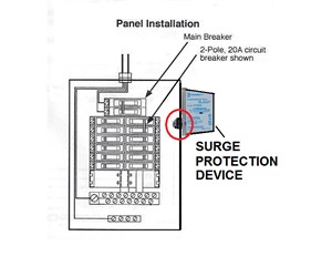
Dc spd wiring diagram. Pv combiners get installed as shown in figure 11 5. The most striking feature of this circuit is its ability to provide full torque even at minimum motor speeds. Dayton dc speed control wiring diagram whats wiring diagram. Pv combiners get installed as shown in figure 11 5. Both leds in the spd should glow blue as a sign that voltage is present in system spd is connected correctly and working and the system is protected. A c spd dc spd full detailed explanation and installation.
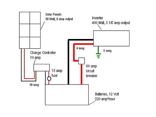
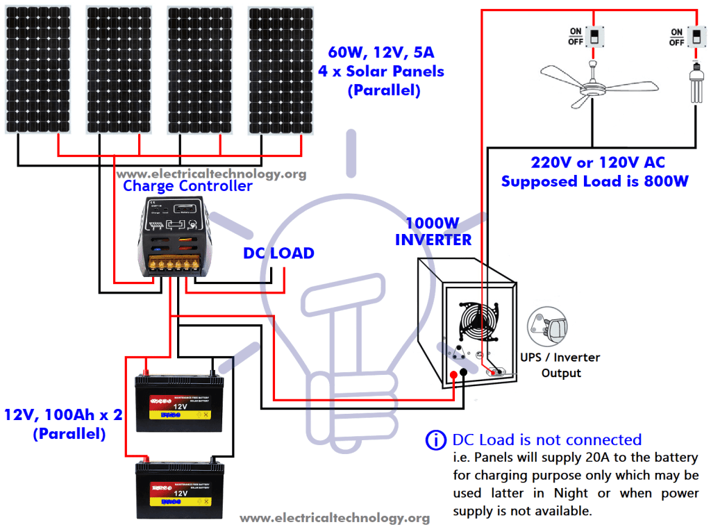
Fuse sizing wire gauge acdc solar power and more. Complete circuit diagram for the motor controller along with the parts list has been included here. The speed is controlled through an externally applied varying dc voltage source. Wiring diagram parts list design worksheet. Apply voltage to spd. 12 dc connect the red wire to pv and the black wire to pv or battery minus.
12 dc connect the red wire to pv and the black wire to pv or battery minus. Both leds in the spd should glow blue as a sign that voltage is present in system spd is connected correctly and working and the system is protected. A wiring diagram is a type of schematic which uses abstract pictorial symbols to show all of the interconnections of components in a very system. Apply voltage to spd.
Gallery of Dc Spd Wiring Diagram