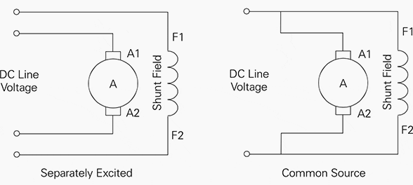
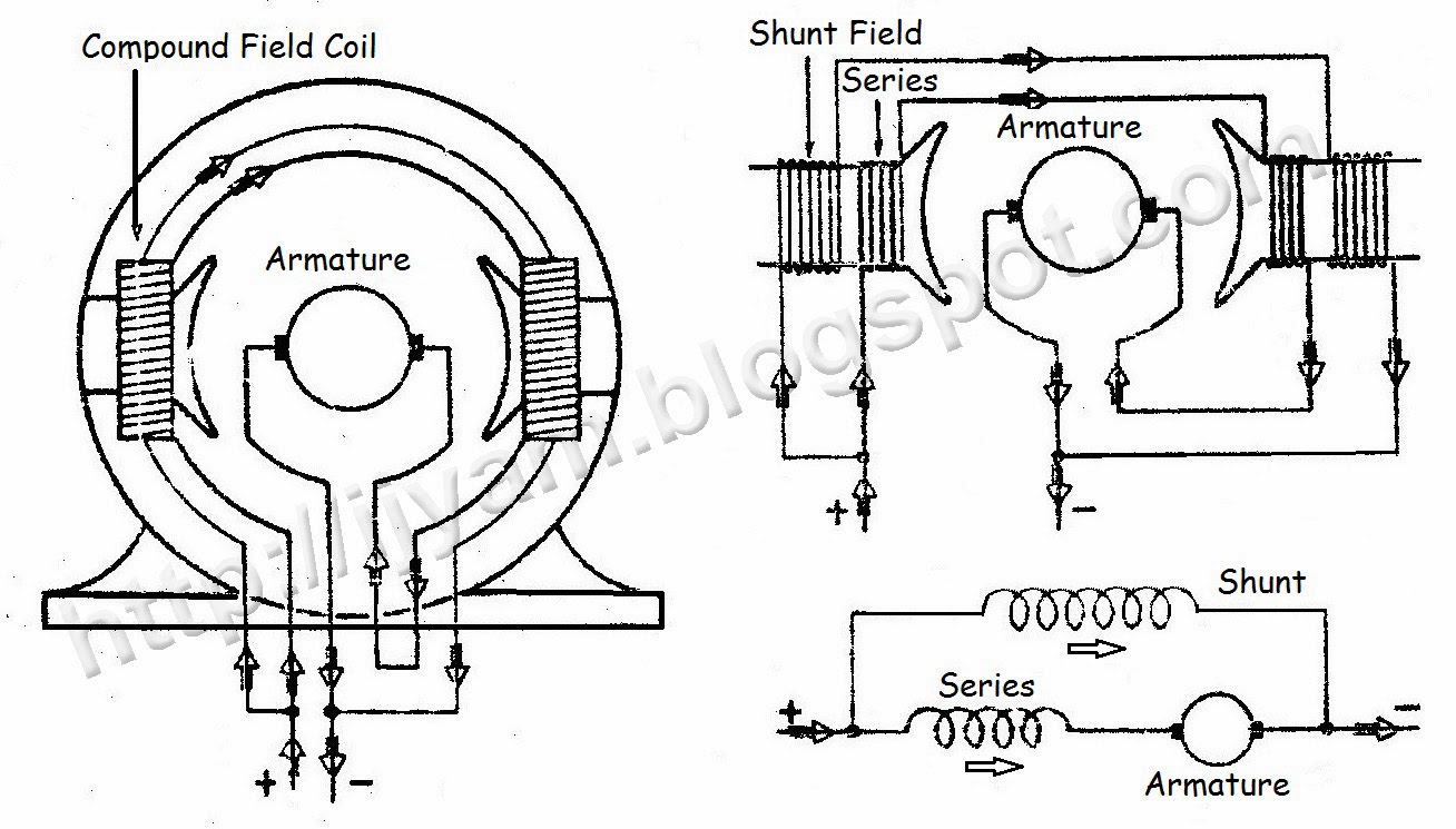
Voltage drop our fourth key variable in wire sizing introduces the factor of the length of the wires into your calculations. Use figure 1 if your motor has a single voltage shunt field.

Controlling A Dc Motor With Arduino Bc Robotics
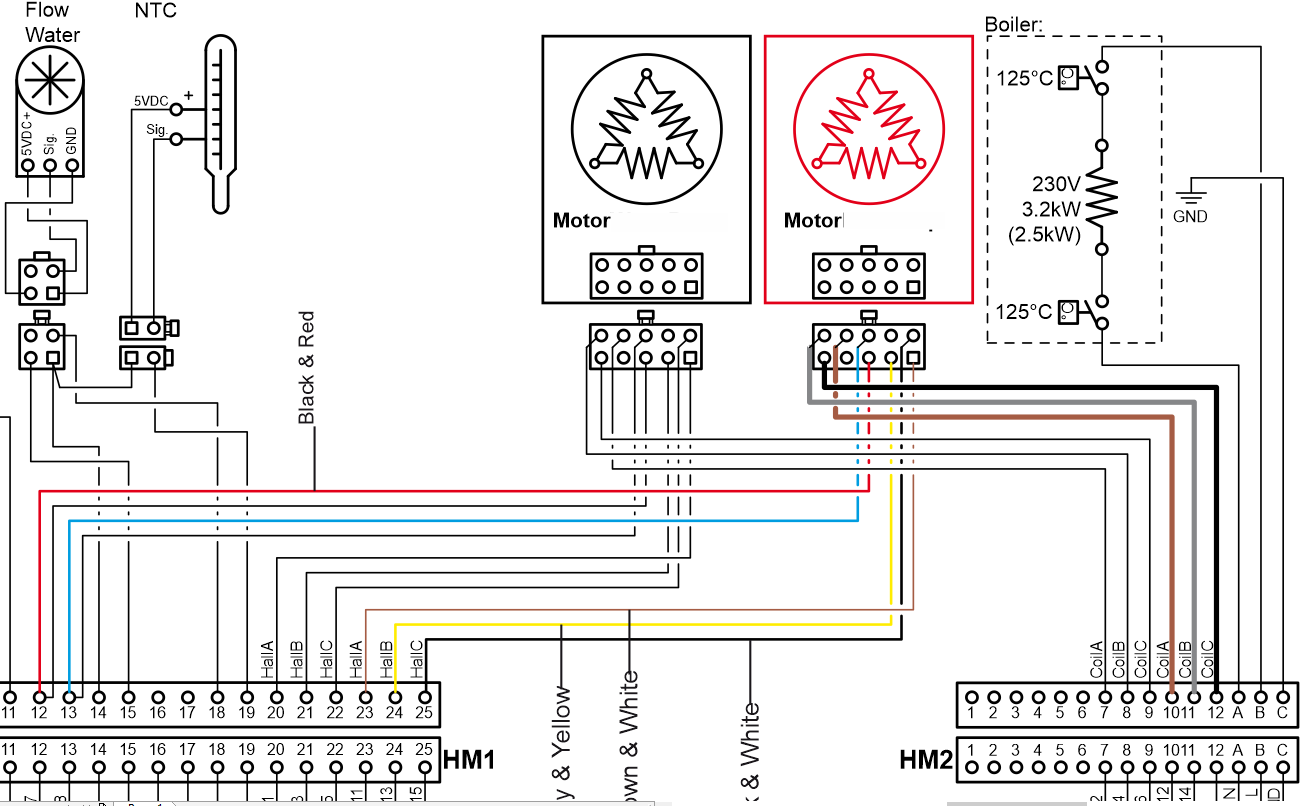
Dc motor wiring diagram 2 wire. Rotating part with permanent magnet ring with 2 n and 2 s poles. That bulletin also includes how to improve the look of a peco point so the more adventurous among you might like to check it out. Connection diagram 07410101 permanent magnet dc 2 wire reversible. As 183 wiring diagram with switch. Ac80 ac90 ac100 single phase motors. Use figure 2 if your motor has a dual voltage shunt field.
The basics of wiring a turnout correctly. Basic wiring for dc current dc electric motor wiring parallel and serial battery connectionhow to use switches relays basic electrical symbols. I prefer dc power. Motor connections your motor will be internally connected according to one of the diagrams shown below. Wye start delta run or pws connection 12 lead dual voltage. And if this is ac motor may be some simple alternating using h bridge l298.
12 lead wye start delta run or pws single voltage assembled in conduit box. Green or green yellow tracer. It does not rotate when dc powered. Page 2 wiring point work special track conditions for dc or dcc 1. Figure 2 illustrates the basic mechanism of a dc motor. Ac80 ac90 ac100 single phase motors.
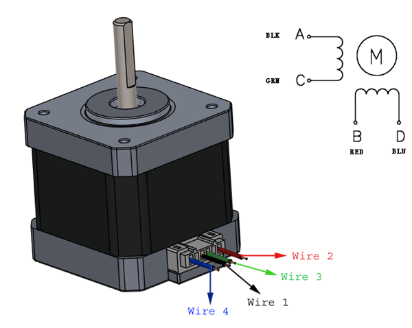
Motor has 2 wires and 4 coils connected in series. I want to make it rotating somehow without much requirements in torque and speed. The two wire circuit in configuration 2 operates as follows. If the single pole switch marked s1 is left open then the liquid level switch in the circuit will now be the control device that turns the motor starter on or off. We also cover this subject in detail in another advice chapter advice 2making peco better. 4 wire reversible psc motor.
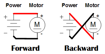
As the magnets are alternately attracted to one coil and repulsed by the other it spins from one to the other and you get circular motion. The longer the wiring run the greater the voltage drop. Each wire has a predictable level of internal resistance so that in a dc circuit you will lose a certain amount of energy thats turned into heat. These connections are in accordance with nema mg 1 and american standards publication 06. If the single pole switch is toggle closed the motor starter will start and stay on for as long as the single pole switch is closed. Motor wiring diagram dc.
2 speed 2 winding single voltage wye connected with current transformers lightning arrestors surge capacitors. To reverse direction of rotation transpose white black leads. If you mount magnets on a spinning shaft surrounded by the wire you have a motor in the diagram below the wire is arranged in two coils.
Gallery of Dc Motor Wiring Diagram 2 Wire