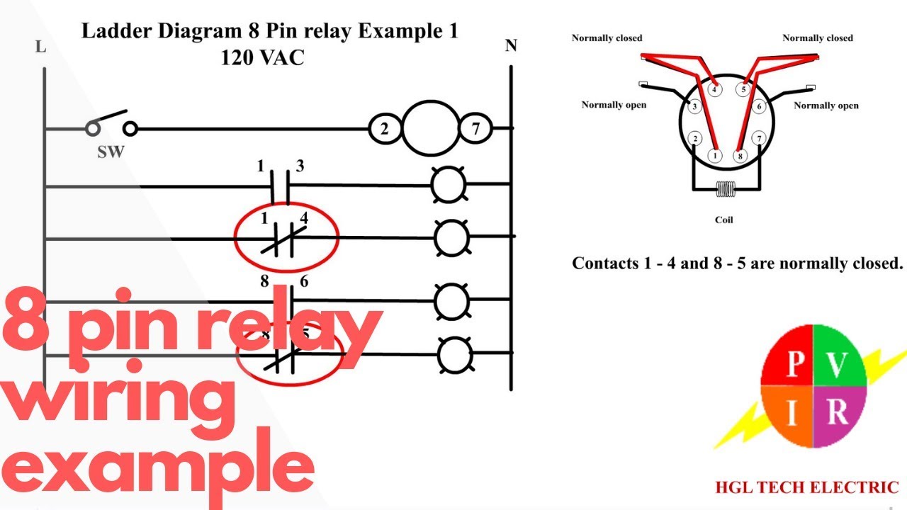
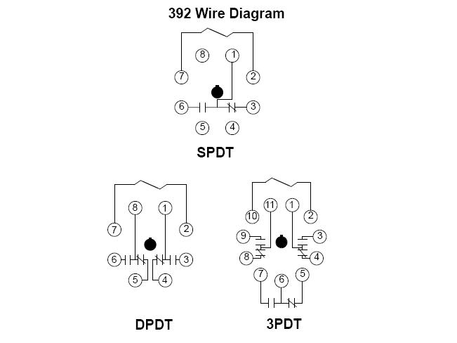
I also have a on button and off button. This pinout image is only a 2 pole diagram for room on the page purposes but you can get the picture here with this one since a 3 pole will just have 1 more set of contacts.

Wiring Help Harley Davidson Forums
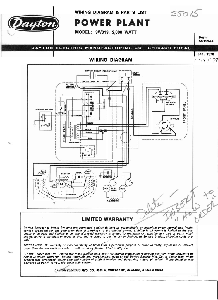
Dayton relay wiring diagram. Every time delay relay has an internal relay usually mechanical with contacts that open close to control the load. Looking for dayton single function encapsulated timing relay 24 to 240vac mounting. The usual aspects in a wiring diagram are ground power supply wire as well as link result gadgets switches resistors reasoning gateway lights etc. A wiring diagram is a schematic which uses abstract pictorial symbols to exhibit each of the interconnections of components in a very system. You are able to easily step up the voltage to the necessary level utilizing an inexpensive buck boost transformer and steer clear of such issues. To check out a wiring diagram initially you have to know just what fundamental elements are consisted of in a wiring diagram as well as which pictorial icons are made use of to represent them.
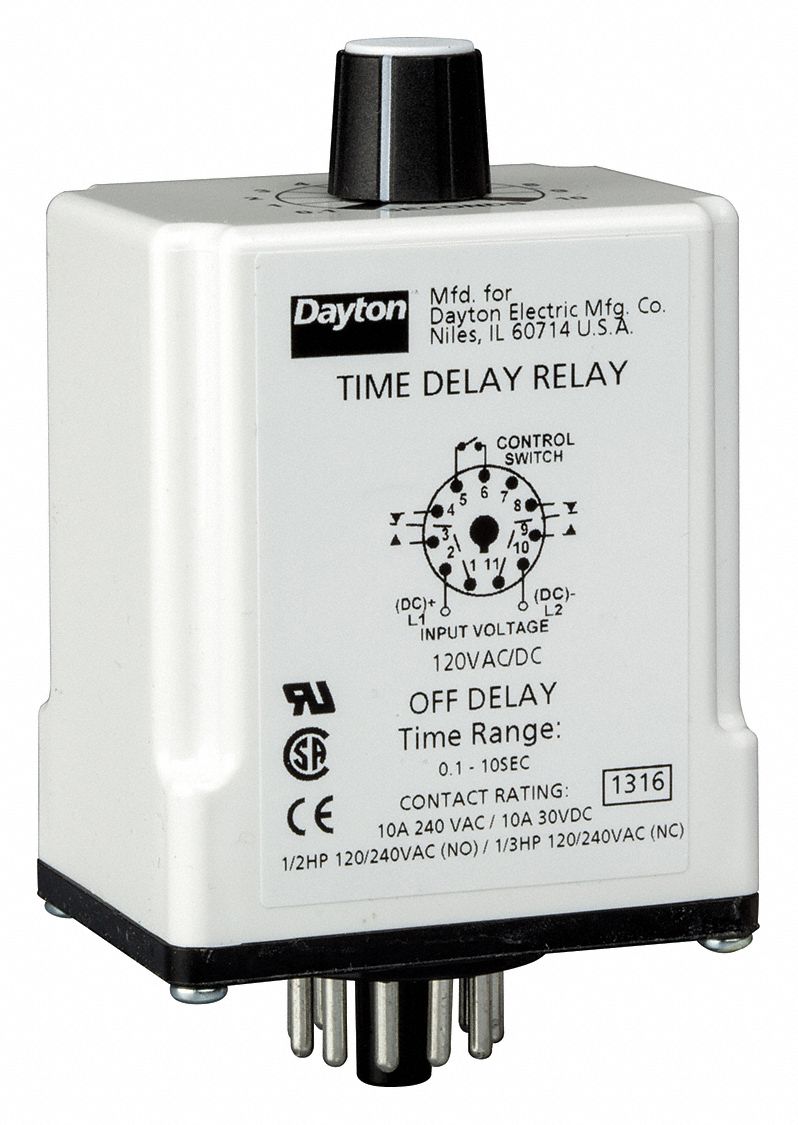
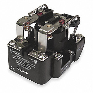
Graingers got your back. Each circuit displays a distinctive voltage condition. Need to wire in a dayton 11 pin time delay relay to pull in a v contactor on a motor starter for it to run for a set time. Dayton relays model 1egc4 description time delay relay terminal s tyle octal base contacts configuration dpdt current ac operated input voltage 120 vac mounting type plug in socket mount features timing adjustment knob output characteristics. Easy online ordering for the ones who get it done along with 247 customer service free technical support more. These guidelines will likely be easy to comprehend and implement.
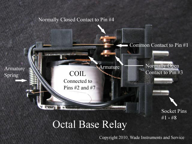
A wiring diagram is a streamlined standard photographic representation of an electric circuit. Variety of dayton time delay relay wiring diagram. They are represented by the dotted lines in the wiring diagrams. Dayton time delay relay wiring diagram whats wiring diagram. It reveals the elements of the circuit as simplified shapes and also the power and signal connections in between the devices. The voltage is the sum of electrical power produced by the battery.
Dayton solid state relay wiring diagram. It is meant to help each of the common consumer in building a correct method. 8 pin relay wire diagram wiring schematic wiring diagram 8 pin relay wiring diagram. Wiring diagram arrives with numerous easy to follow wiring diagram instructions. Any help would be greatly appreciateddayton time delay relay wiring diagram wiring librarydayton solid state time delay relay 6a wiring diagram fixya. The square relay pinout shows how the relay socket is configured for wiring.
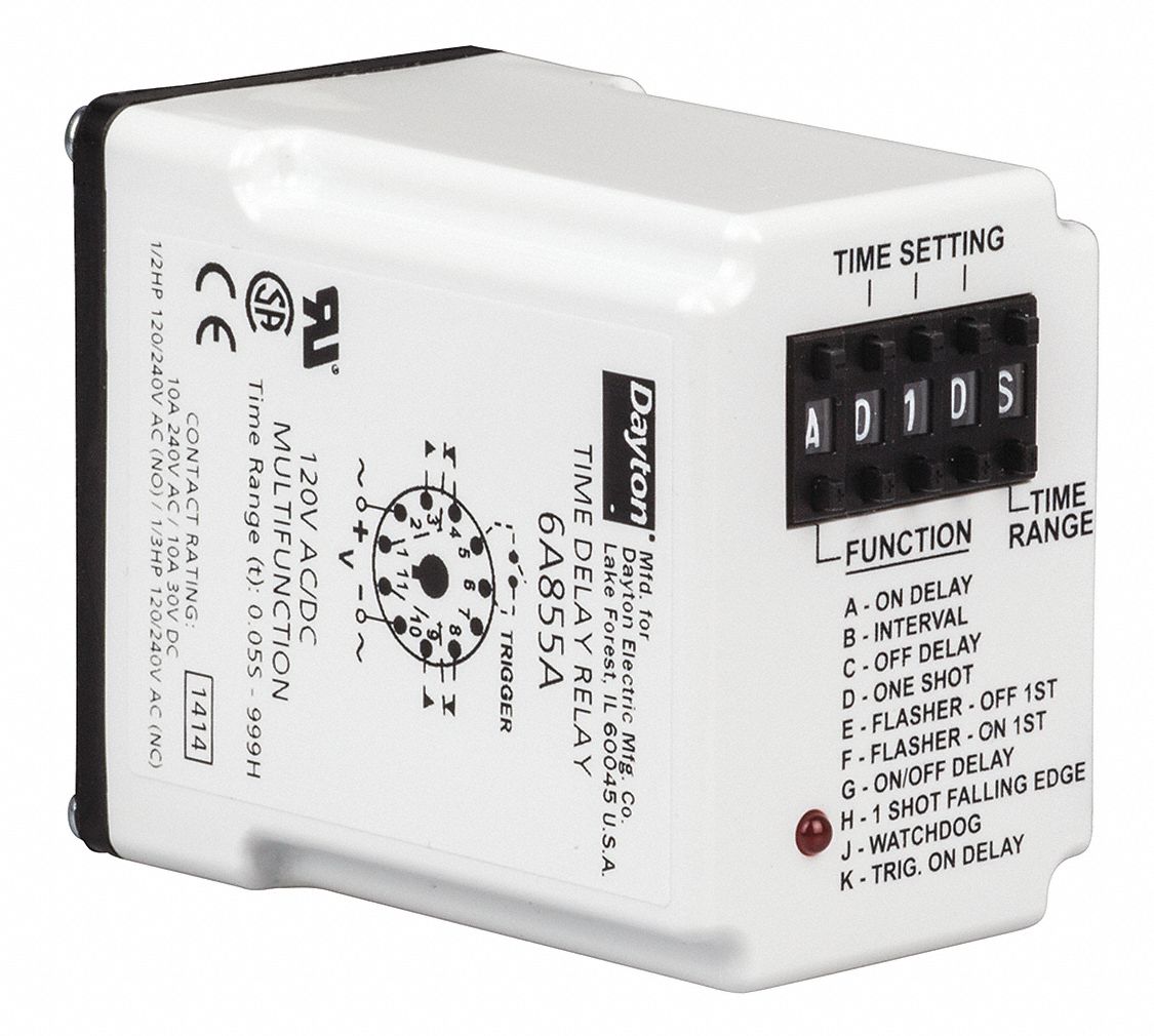
Note that the user must provide the voltage to power the load being switched by the output contacts of the time delay relay.
Gallery of Dayton Relay Wiring Diagram