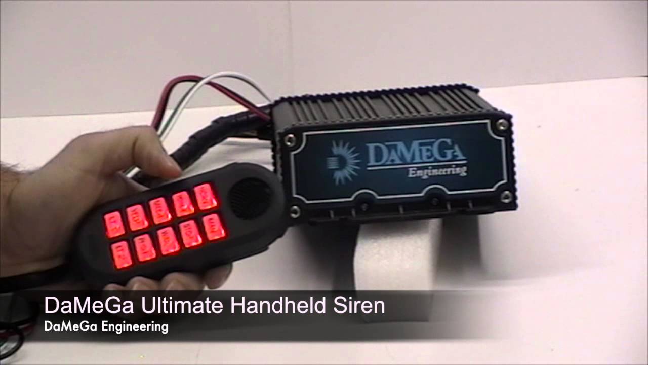
The system is controlled using a hand held controller. This controller is comprised integrated into the siren system as shown in the wiring diagrams on.

Ko 8329 De Mega Siren Wiring Diagram Free Diagram
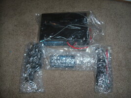
Damega intel siren wiring diagram. The back of the intell siren power supply is physically labeled as shown in the diagram. 1 extend the red wire from the positive post on the vehicles battery to the 12vdc input on the back of the amplifier unit by using a 12 gauge wire. 2 extend the black wire from the ground post on the battery to the negative input on the back of the amplifier unit using a 12 gauge wire. Labels nc state fight song lyrics old avon mens cologne jensen uv10 wiring diagram toddler weekly lesson plan template laura day trading spaces district the intel siren by damega engineering is an all in one control box and siren wire blocks are standard for mounting making installation easy. This siren features a remote mount brain with keypad style controller. Check out our damega intel handheld siren.
It boasts standard tones such as wail yelp hilo and manual as well as the new damega mechanical tone. The intell siren functions as an all in one control panel. Damega light bar wiring diagram wiring diagram is a simplified satisfactory pictorial representation of an electrical circuitit shows the components of the circuit as simplified shapes and the faculty and signal links between the devices. Damega intel handheld siren. Damega intel handheld siren wiring diagram. Fuse at 25 amps.
The intel hub radio show 1 26 1 atlantis radio. The labels shown on the back of the power supply a h allow for control of vehicle.
Gallery of Damega Intel Siren Wiring Diagram