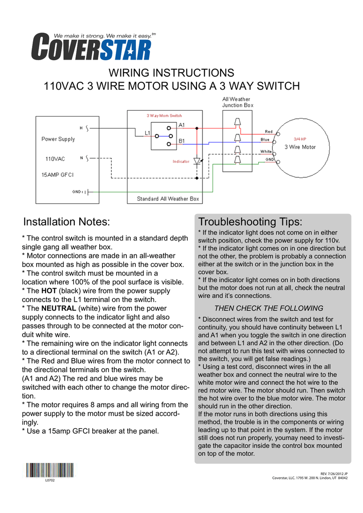
Wiring the electrical switch the control switch mush be mounted in an all weather box in a location where 100 of the pool is visible. The top switch is easier to adjust.
Auto Pool Cover Motor Wiring Bypassing Limiter Ridgid Forum
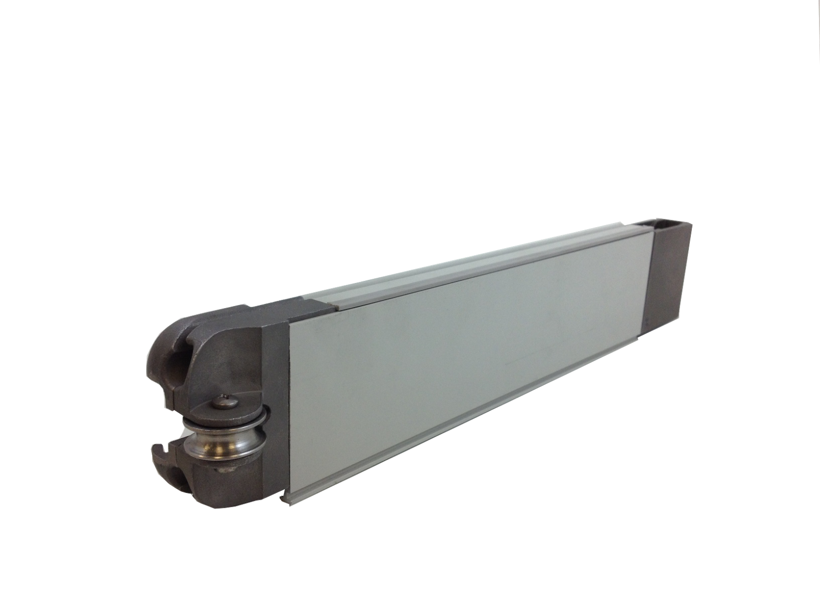
Coverstar switch wiring diagram. In this diagram two 3 way switches control a wall receptacle outlet that may be used to control a lamp from two entrances to a room. The hot black wire from the power supply connects to the l1 terminal on the switch. Pully brackets order parts. The switches are rated at 15 amps for 110 volts. Either switch will work. Wiring the electrical switch connect the electric switch by wiring the neutral wire from the power supply the white wire from the motor and one of the wires from the indicator light together using a wire nut.
Drive gear assemblies. Product diagrams by manufacturer. Electrial wiring diagram and details and shown below. Will the switch work for 24 volt wire can the switch be converted fro can you go from 110 two 12 volt wiring for the switch and how do you go from 110 to 12 volt. The source is at the sw1 where the hot is connected to. Shayne c on oct 15 2019.
Connect the ground wires from the power supply and the motor. Three wire cable runs between the switches and the outlet. Rope reel assembly. Switch must be mounted in a position with a full view of the pool. Find current and past cover pools owners manuals including the t4 and save t3 automatic pool covers step saver manual pool cover and autosave spa cover. The other wire is to be joined with the white neutral wires.
This circuit is wired the same way as the 3 way lights at this link. After final wiring if the cover movement doesnt agree with the cover uncover labels on the front of the switch just reverse the positions of the red and blue wires on. Coverstar leviton key switch assembly complete with light std a0605 19299. The remaining wire on the indicator light connects to a directional terminal on the switch a1 or a2. The wire with the forked end terminal is attached to the switch at the red directional screw. The neutral white wire from the power supply connects to the indicator light and also passes through to be connected at the motor conduit white wire.
Rotary limit wiring diagram note. A1584 ug left a1583 ug right. 3 way switched outlet wiring.
Gallery of Coverstar Switch Wiring Diagram