Wiring diagrams help technicians to see how the controls are wired to the system. Wiring diagrams sometimes called main or construction diagrams show the actual connection points for the wires to the components and terminals of the controller.
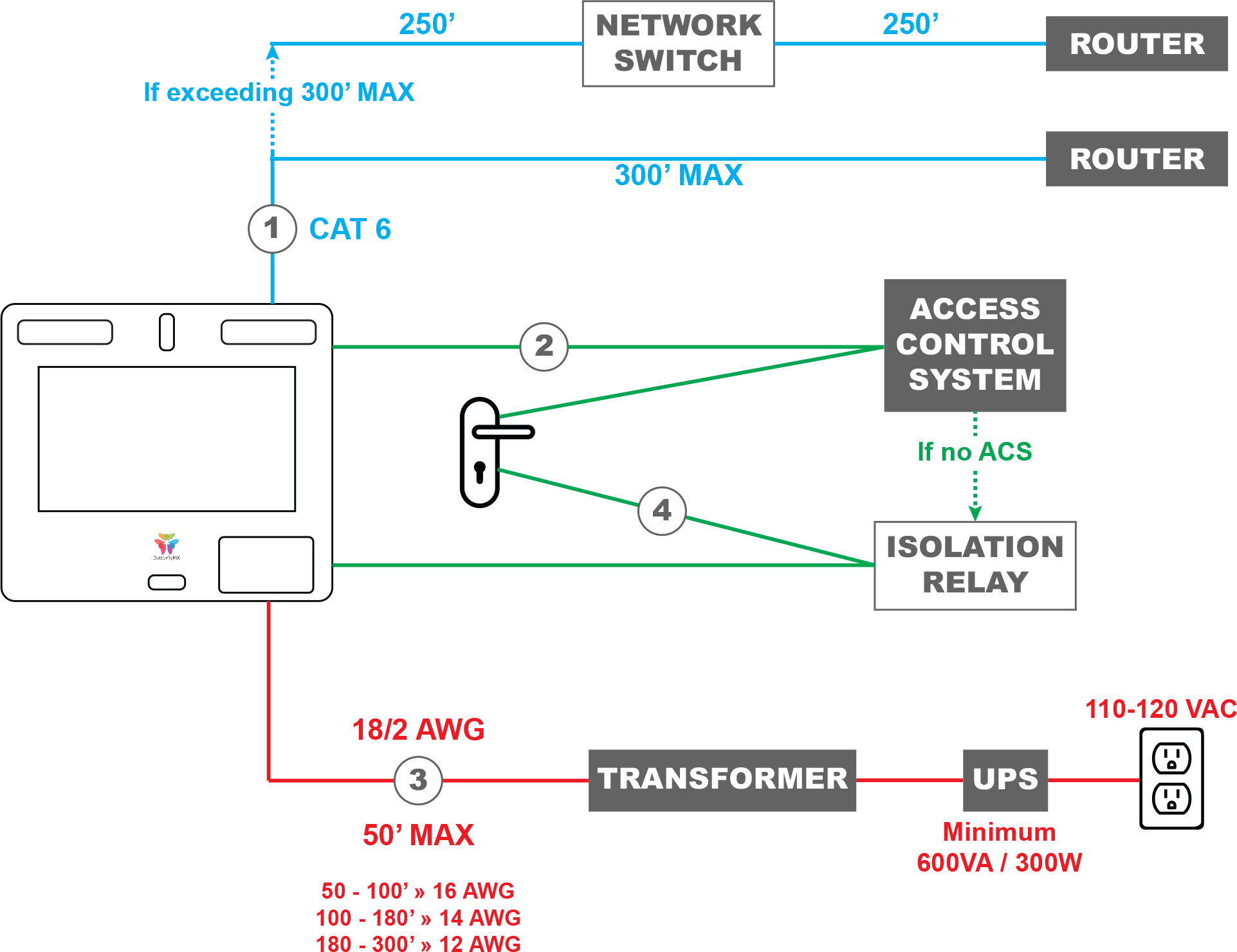
Wiring A Butterflymx Smart Intercom Directly To An Electronic
Control wiring diagram. Search the lutron archive of wiring diagrams. Drawing wiring and power control circuit diagrams on pc the 10 basic rules learn the 10 things you need to know in order to draw electrical wiring diagrams plc diagrams and power control circuit diagrams quickly and effectively using an advanced electrical design software as pcschematic automation. To help illustrate the differences between wiring diagrams and schematics a basic control circuit will first be explained as a schematic and then shown as a wiring diagram. Icons that stand for the components in the circuit and also lines that represent the connections in between them. Many people can read and understand schematics known as label or line diagrams. Breakdown of colors and terminals thermostat wiring diagram for ac unit.
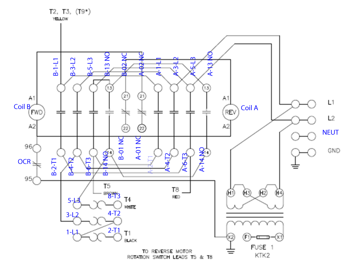
To find a diagram for a specific product or system please use the drop down menus below. Specify the product or system. Three phase motor connection schematic power and control wiring installation diagrams. Electrical wiring layouts are made up of 2 things. Red wire for air conditioner control power hot white wire for heating system if so equipped g wire for fan control how to wire an air conditioning thermostat. Icons that represent the elements in the circuit and lines that stand for the connections between them.
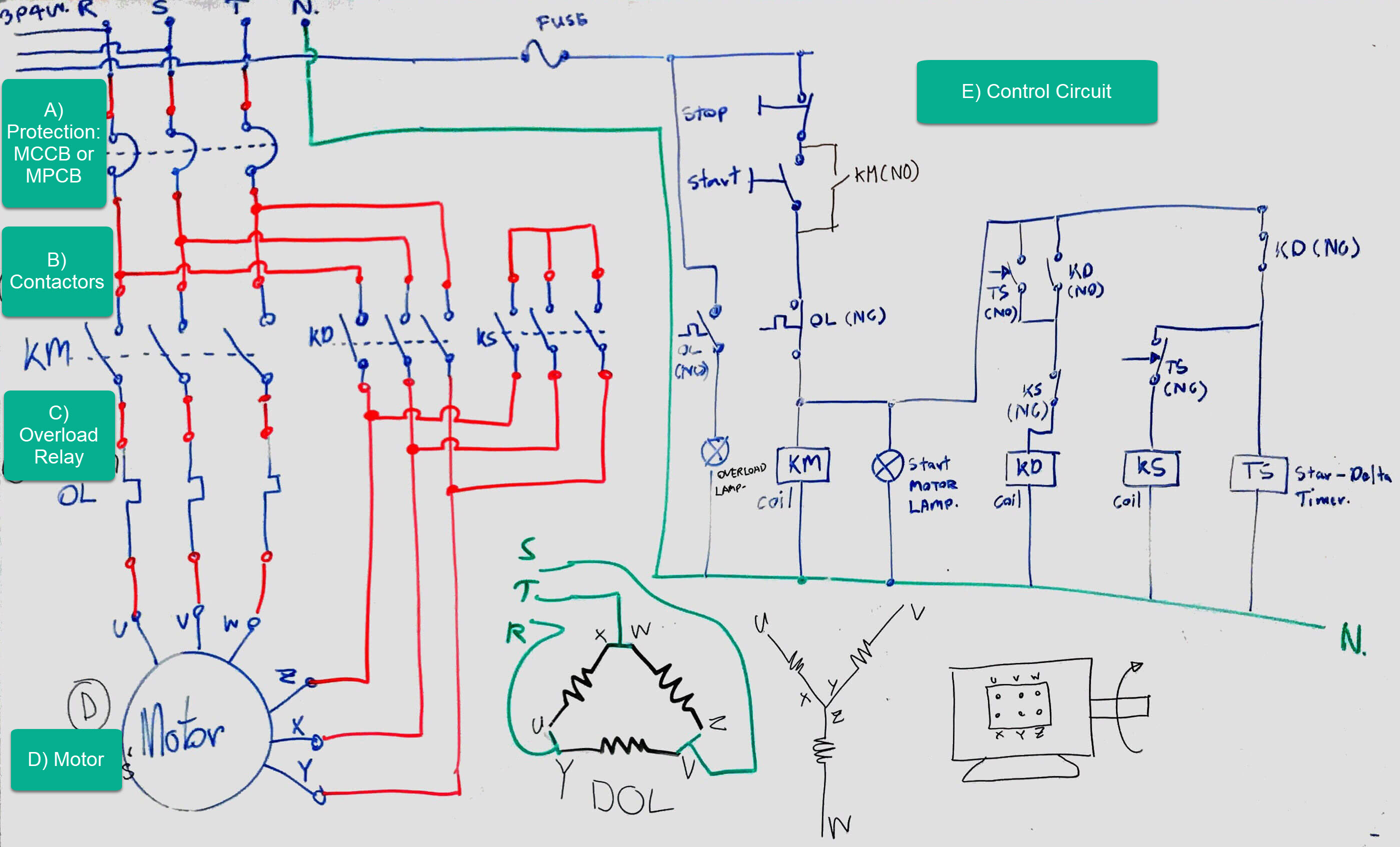
Three phase motor connection stardelta without timer power control diagrams. Y terminal for yellow wire air conditioning thermostat wiring. Control wiring carries low levels of current because not much current is required for control purposes such as energiz. See how lutrons superior light control enhances the many facets of your home and workplace. This type of diagram is like taking a photograph of the parts and wires all connected up. A wiring diagram is a type of schematic which utilizes abstract photographic symbols to reveal all the affiliations of elements in a system.
Control wiring control wiring as its name implies has as its main purpose transmitting electricity used for control purposes. Star delta y δ 3 phase motor starting method by automatic star delta starter with timer. Wiring layouts are made up of two things. They show the relative location of the components. Wiring diagrams show the connections to the controller. A wiring diagram is a type of schematic which utilizes abstract photographic signs to show all the interconnections of elements in a system.
Wiring diagrams show components mounted in their general location with connecting wires. These diagrams show the actual location of parts color of wires and how they are connected. A wiring diagram is used to represent how the circuit generally appears. Find inspiration through rich visualizations of lutron design.
Gallery of Control Wiring Diagram