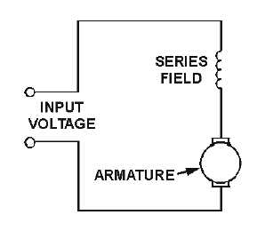
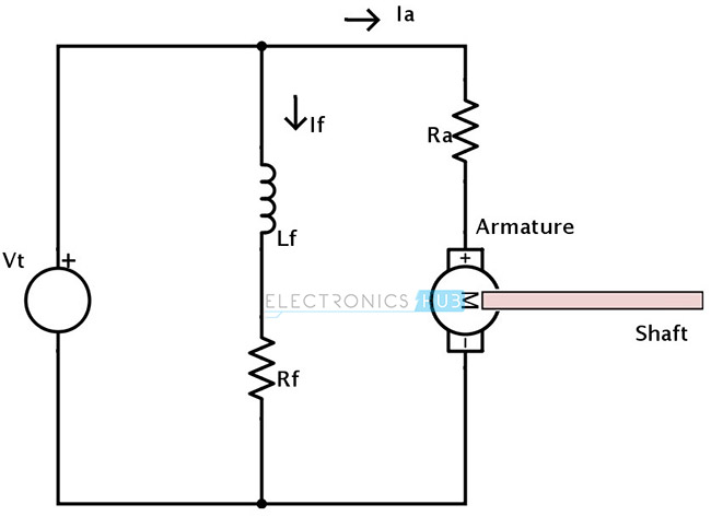
Shunt wound dc motor wiring diagram wiring diagram is a simplified standard pictorial representation of an electrical circuit. This type of dc motor combines both series field and shunt field included as part of the internal components of the motor.

Shunt Wound Dc Motor Schematic Dc Generator Chapter Ppt Video
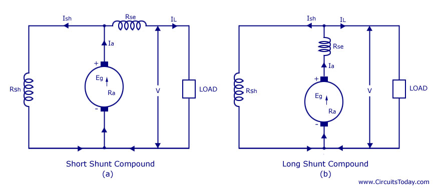
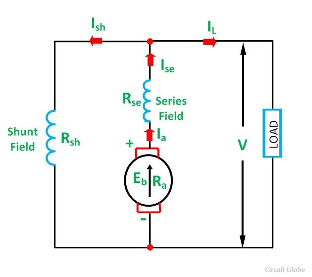
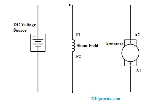
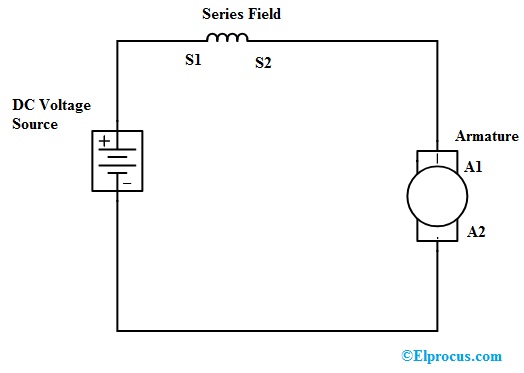
Compound wound dc motor wiring diagram. Compound dc motor connection the method of connection for a compound wound direct current motor is shown in figure 3 below. I am also looking for information on controlling one of these motors with pwm pulse width modulation. A wiring diagram usually gives opinion virtually the relative outlook and contract of devices and terminals upon the devices to put up to in building or servicing the device. A dc motor having both shunt and series field windings is called a compound motor. Use figure 2 if your motor has a dual voltage shunt field. A compound wound dc motor also known as a dc compound motor is a type of self excited motor and is made up of both series the field coils s 1 s 2 and shunt field coils f 1 f 2 connected to the armature winding as shown in the figure below.
In cumulative compound motor the flux produced by both the. Use figure 1 if your motor has a single voltage shunt field. How to wire a dc series motor and how to reverse its rotation. Motor wiring diagram dc. The connection diagram of the compound motor is shown below. These connections are in accordance with nema mg 1 and american standards publication 06.
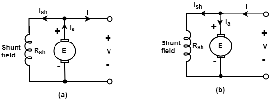
Motor connections your motor will be internally connected according to one of the diagrams shown below. It shows the components of the circuit as simplified shapes and the facility and signal contacts together with the devices. The compound motor is further subdivided as cumulative compound motor and differential compound motor.
Gallery of Compound Wound Dc Motor Wiring Diagram