Wiring diagram to connect npn open collector proximity sensors. Do not use this machine for other than its intended use.
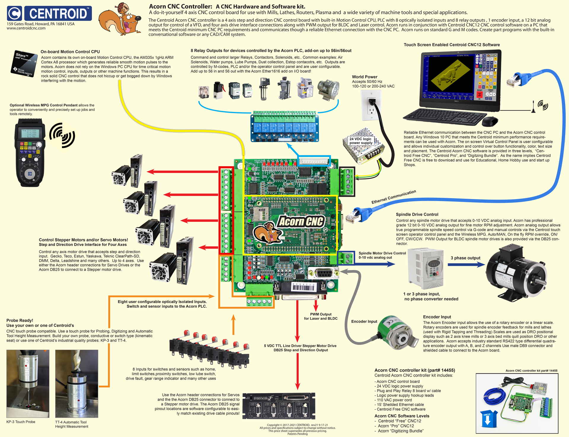
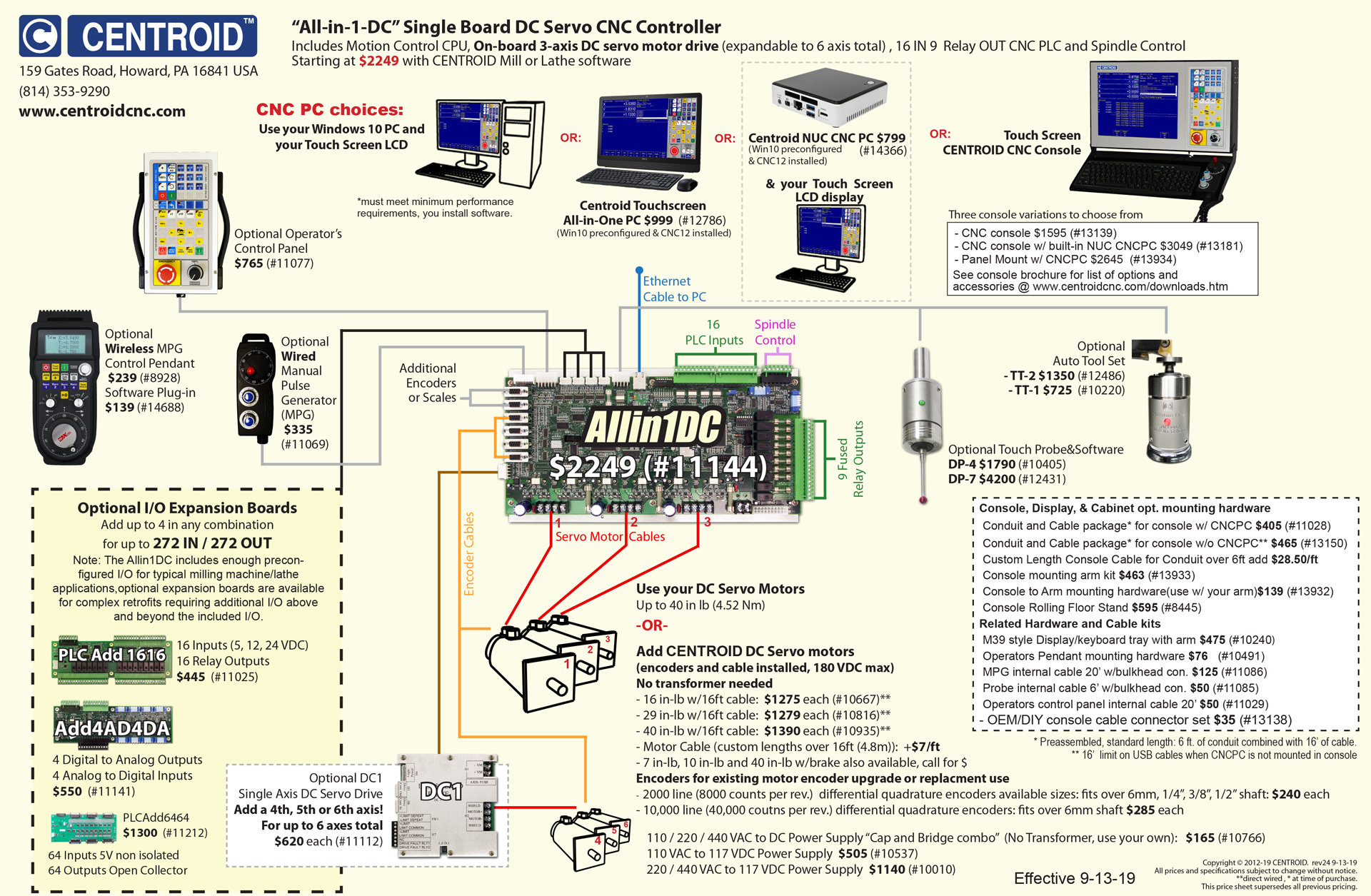
Acorn Cnc Controller Step And Direction 4 Axis Cnc Control
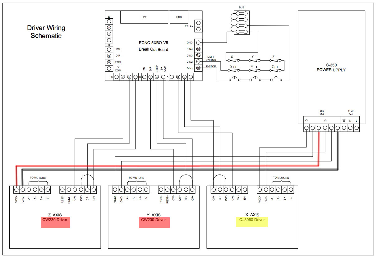
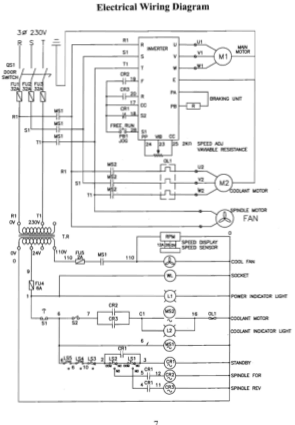
Cnc wiring diagram pdf. If you are not familiar with the proper and safe operation of a cnc routing machine do not use until proper training and knowledge have been obtained. Com parallel cable. The bellow wiring diagrams require setting the inputs to use pull down resistor. 5 axis cnc breakout board step dir en 5v 24vdc com step dir en 5v b b a a driver board step dir en 5v 24vdc com step dir en 5v b b a a driver board step dir en 5v 24vdc com step dir en 5v b b a a driver board step dir en 5v in1 x axis limit nema 23 stepper motor x axis y axis z axis a axis x axis nc. Tig en tighten tig en. Workbee cnc wiring commissioning 10 31 cnc xpro wiring a.
Siemens operator manual diagnostics guide operationprogramming operators guide short guide operation measuring cycles fundamentals advanced programming short guide programming cycles programming siemens maintenance manual siemens touch probe. 160mm 70mm 300mm 48mm 330mm. The wiring of the parallel breakout board from the output terminals to the driver digital pulse step pulse and direction lines are explained. This cnc routing machine is designed and intended for use by properly trained and experienced personnel only. Pinnerzy uwielbiają również te pomysły. Siemens operator manual siemens maintenance manual advanced feed forward.
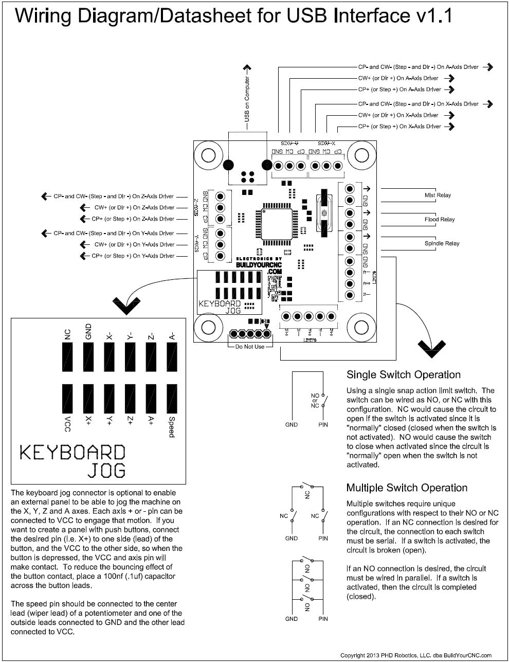
Wiring diagram for power supplies v posv c v com gnd l n l n l n switch mode psus 48 volt with our low inductance nema 23 stepper motors page 3. Fanuc wiring diagrams. 81 connecting switches or push button. If used for other. Wiring diagram for power supplies v posv c v com gnd l n l n l n switch mode psus 48 volt with our low inductance nema 23 stepper motors page 3. Go to the new parallel breakout board to get more information and the wiring diagram.
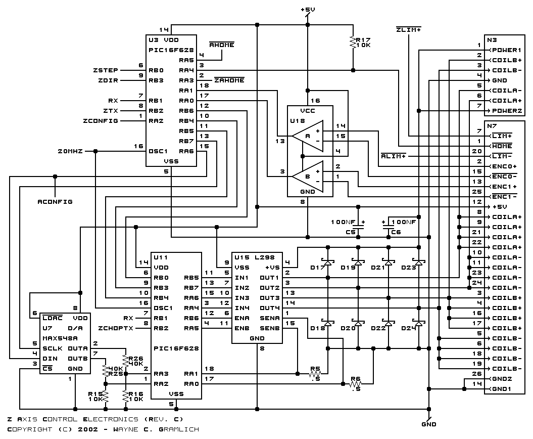
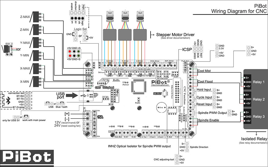
If you have the bluetooth adaptor also attach the provided capacitor with the correct orientation with regards to the positive and negative side. X axis wiring diagram yel blk wht brn red blu org grn a a b b vcc gnd p1 p3 p2 vcc gnd vcc gnd vcc gnd v c c g n d psu 5v regulated 500ma. M5x10 tv15 42mm 28mm e e oo e e 58mm zaxis spindle xaxis yaxis. Wiring diagram to connect switches 82 connecting npn sensors. X axis wiring diagram yel blk wht brn red blu org grn a a b b vcc gnd p1 p3 p2 vcc gnd vcc gnd vcc gnd v c c g n d psu 5v regulated 500ma. The new parallel breakout board appears a bit different but the process of wiring and testing is the same.
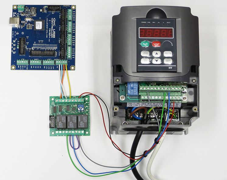
Operation of your cnc or automated machinery. The below wiring diagrams are examples any input can be used for the connections. Following the wiring diagram above strip and connect the second psu output power cable to the power input terminal on the cn c xpro. Operation of your cnc or automated machinery.
Gallery of Cnc Wiring Diagram Pdf