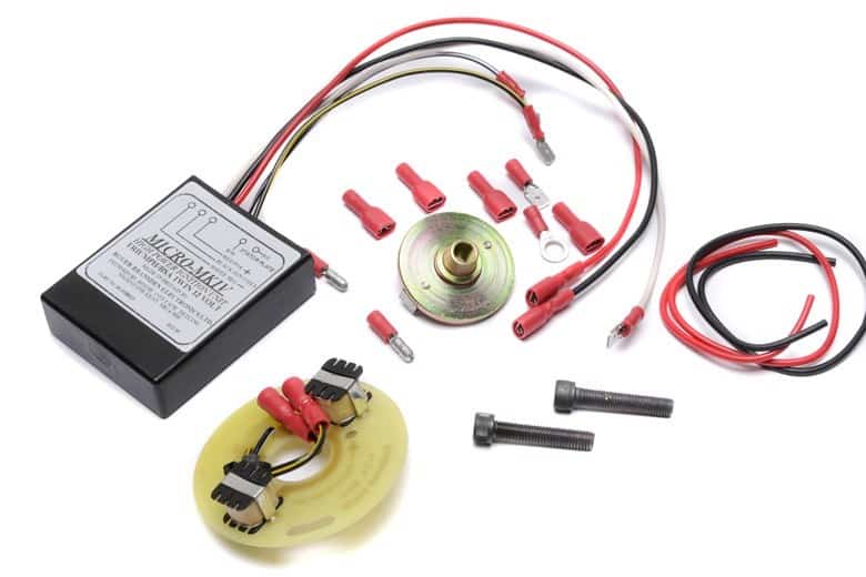
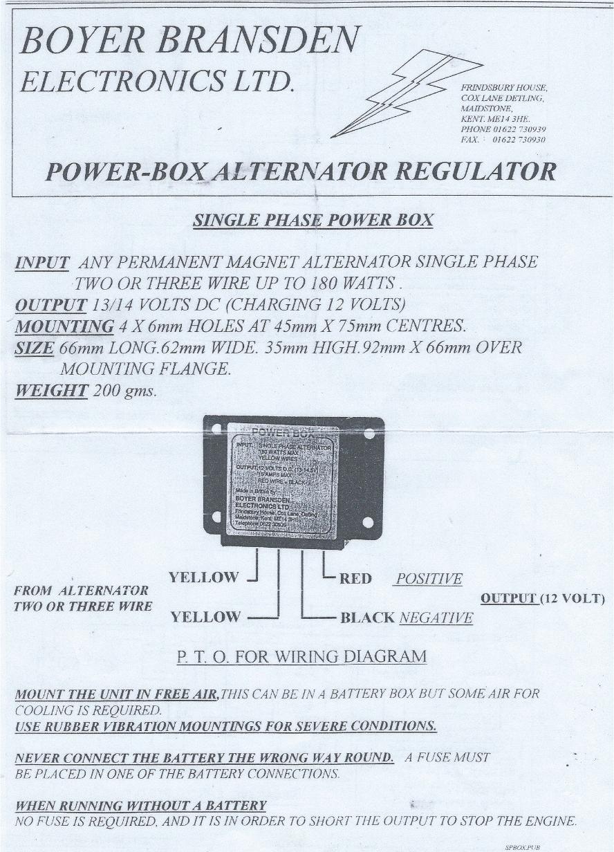
Boyer bransden single phase power box. Alternator regulator three phase 3 wire 12 volt.
Terry Macdonald
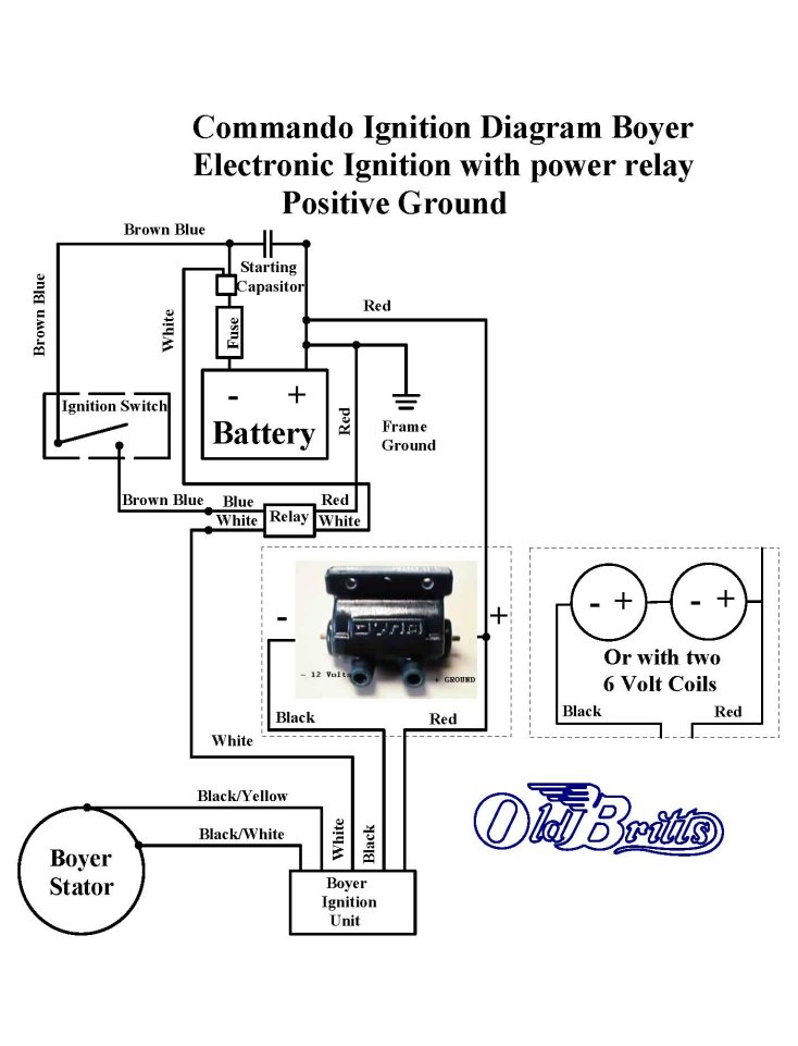
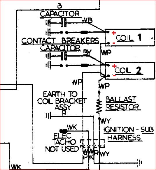
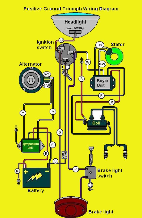
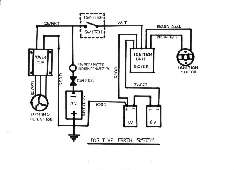
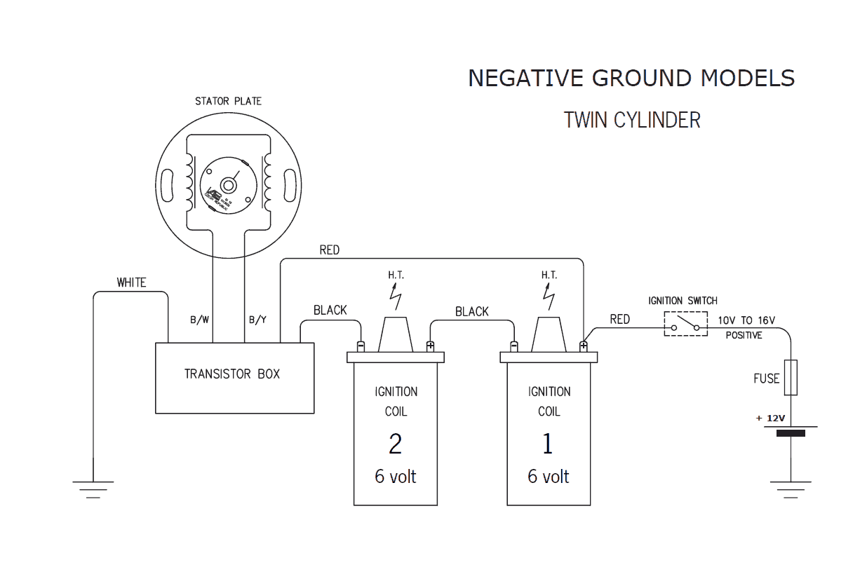
Boyer wiring diagram. Wiring diagram for triumphbsa with boyer ignition. Many thanks to tim bondo bandit return to tech tip index. For mk3 commandos with a boyer ignition a power relay will help eliminate back firing since the boyer really likes. Wiring diagram for triumphbsa with boyer ignition. The same point to which the coil earthing wire feeds. 18 connect the black wire from the transistor box to the terminal of the right hand ignition coil.
We will breake out the wiring into self contained groups ignoring all components except what is included in that group. This diagram is not to be reproduced or used on any site without permission by rask cycle. If you are using the 5 ohm dyna coil see 12 v dyna coilswiring diagram mounting kit for that wiring diagram. The battery or battery eliminator must be able to supply between 11and 16volts under load brake and head light on. The charging system stator rectifier diode and rotor must be in good condition. This article will hopefully simplify the wiring on norton commandos.
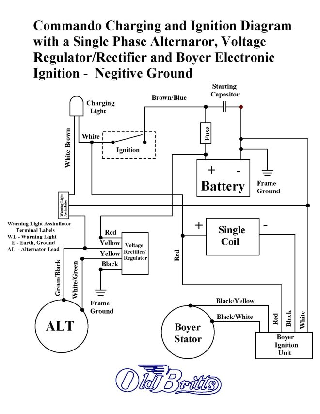
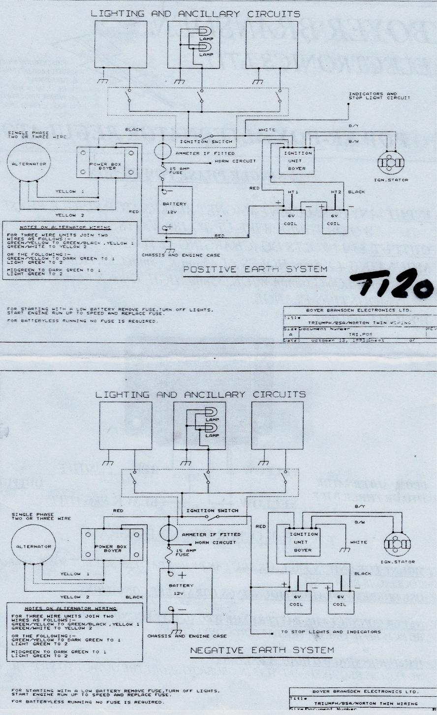
Alternator regulator three phase charging light negative earth. This is a straightforward power box. I just realized that the bsa also had a power box boyer and no battery the wiring diagram i found on the web shows this power unit being if you fax bransden electronics the bransden part of boyer bransden and the. Single phase powerbox with lighting delay alternator regulator. Many thanks to tim bondo bandit tech tips index. 12 connect the black yellow wire from the transistor box to the black yellow wire that.
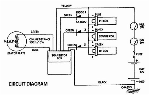
Alternator regulator bi phase 3 wire 12 volt. 19 connect the white blue wire the one removed from the ballast resistor to the white wire from the transistor box. 12 connect the black wire from the transistor box to the negative terminal of ignition coil no3. Alternator regulator single. Rask cycle tech tips. 1the triumph bsa or norton twin boyer electronic ignitions can run in positive or negative ground systems.
11 connect the white wire from the transistor box to one of the negative feed wires from the ignition switch. What does it do. This diagram is not to be reproduced or used on any site without permission by rask cycle. Diagram by tim dodge. Diagram by tim dodge. 11 connect the red wire from the transistor box to the positive terminal of ignition coil no1 this is the same connection as used in step 8 the coil having a double connector.
See appropriate wiring diagram. 19 connect the white blue wire the one removed from the ballast resistor to the white wire from the transistor box. Positive ground wiring diagram. These were taken off the ignition coils in step 5 above. Single phase powerbox 12v 114k pbox00109. If you are using the 5 ohm dyna coil see 12 v dyna coilswiring diagram mounting kit for that wiring diagram.
Gallery of Boyer Wiring Diagram