The second part involves the control circuits. The first part deals with the power circuit connections because starters consume and alternators produce great amounts of power.
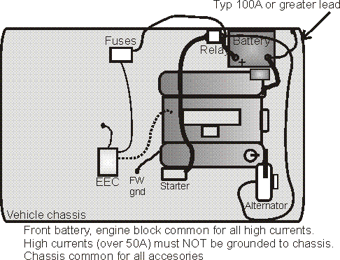
Grounding Negative System
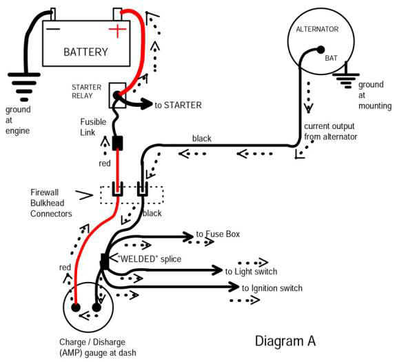
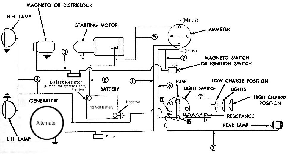
Battery starter alternator wiring diagram. The way its was hooked up is 1 wire from starter to 175 mega fuse 1 to fuse box and the 1 grounding the starter to solenoid and ground to battery. Starters are turned on and off and alternator output is. As you see there are the three phase alternator is used in the car. Each part ought to be set and linked to other parts in particular way. Here the basic internal circuit diagram of the car alternator and the wiring diagram of the alternator with battery is given below. If not the arrangement will not function as it ought to be.
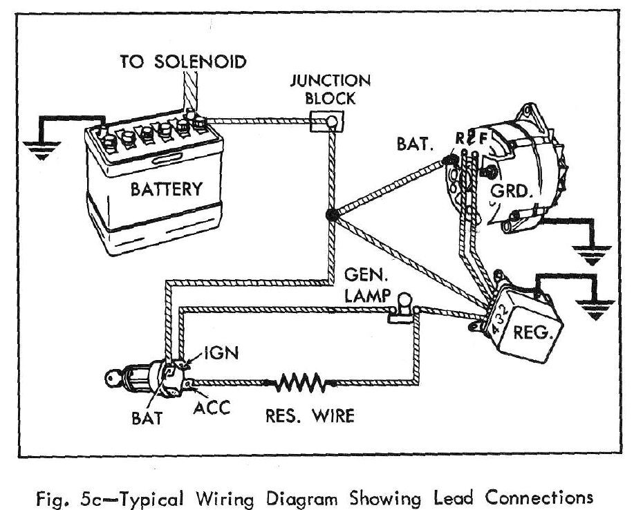
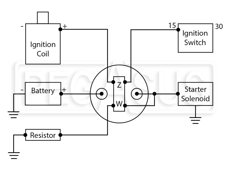
Alternator to battery wiring diagram alternator to battery wiring diagram every electrical arrangement consists of various different parts. The three phase alternator has two parts stator and rotor. The mega fuse has 2 posts 1 from positive 1 from starter and 1 from alternator. When i test the voltage it reads 0 which makes me think its not hooked up right. If your unit requires a separate ground run a short wire from the alternator to a convenient point on the engine block or the chassis. Da plug connects to the coil terminal through the ballast resistor if there is one.
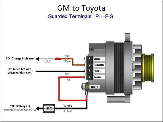
The headlights dashboard lights radio and interior lights all rely on the alternator to keep the battery charged and the car operating. The process for wiring a starter and an alternator on a car is divided into two parts. This wiring configuration will excite the alternator to start charging when the engine is running at low rpms. Alternator demo wiring connection to battery. Charge wire connects from the alternator to the battery through the the resistor or directly to the key switch itself switched side.
Gallery of Battery Starter Alternator Wiring Diagram