Verify the ignition wire by measuring the operating voltage while the key is turned to the on or start position the voltage should read 0 vdc when the key is in the off position and typically between 11v and 14v when in the on position. Our company sells gps tracking devices for 119 that includes service.

Ey 7667 Wiring Harness Diagram Kenwood 16 Pin Wiring Harness
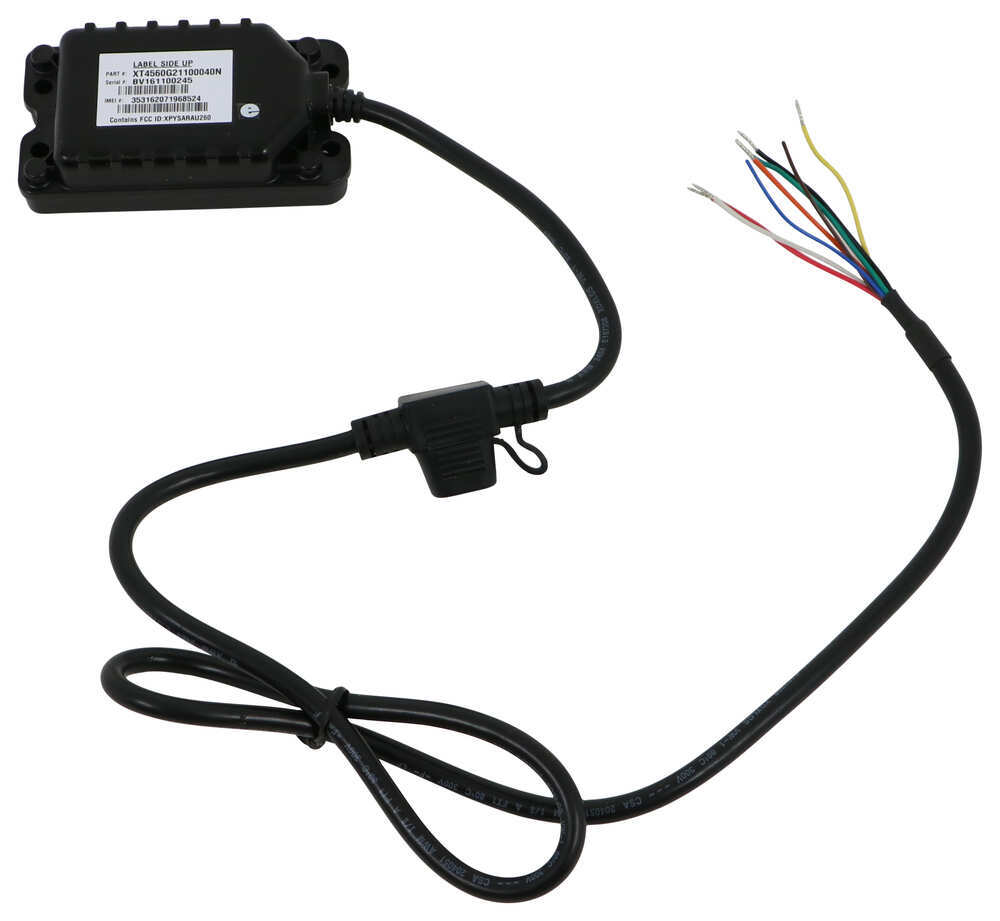
Aware gps wiring diagram. For a more discreet installation or for vehicles without an obd ii port such as electric vehicles our wired gps tracker is the perfect solution. Our gps tracking device is 119 that includes service. Gps trackers for cars trucks fleets that install in seconds. Locate the vehicles ignition wire reference the vehicles wiring diagram in order to locate. Wired gps vehicle tracker. Can be hidden to prevent tampering.
Call direct at 602 478. Help center home installation. Wiring diagram in order to locate. Youll have to make sure that the radio receiver is in a place that will see the satellites for best results. Collection of calamp gps wiring diagram. Call us direct 602 478 3303call 602 478 3303 or visit.
Perfect for heavy duty vehicles such as semis waste haulers buses etc. This video will show you how to connect the power and ground wires for a vehicle gps tracking device. Awaregps wired vehicle trackers can be installed by connecting 3 simple wires. Gps fleet management tracking made easy. Installs with a simple 3 wire installation. Click here for resources to help you manage your fleet during the covid 19 pandemic.
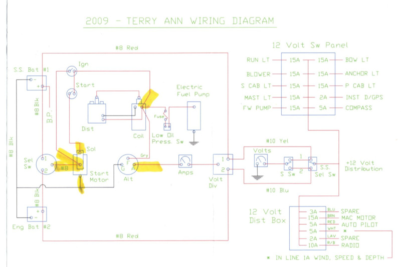
Wired installation avoids tampering and the device can be completely concealed. A wiring diagram is a streamlined standard pictorial representation of an electrical circuit. Awaregps the easy affordable gps tracking system. Also new on the market are gpsdsc handheld vhf radios but be aware that handhelds have limited transmitting power. It reveals the elements of the circuit as simplified forms and also the power as well as signal connections between the gadgets. Our wired gps tracker.
4 best most expensive. Get an integrated system that includes a gps antenna chartplotter and radio. Verify the ignition wire by measuring the operating voltage while the key is turned to the on or start position the voltage should read 0 vdc when the key is in the o position and typically between 11v and 14v when in the on position. Gps devices need to wired correctly and put in a properly location to work properly.
Gallery of Aware Gps Wiring Diagram