24v green led is on 3. If the pop up blocker is turned on in your browser you are not able to view the wiring diagram.
Auma Actuator Connection Diagram F8 Wiring Diagram
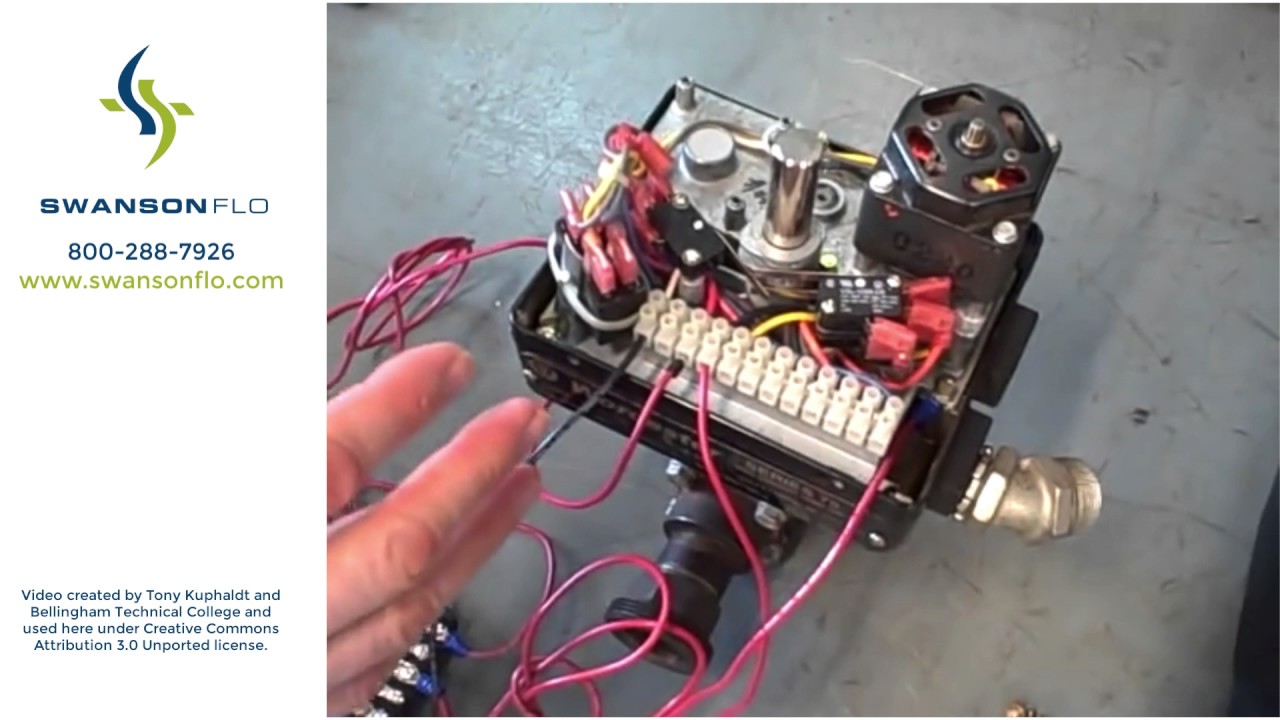
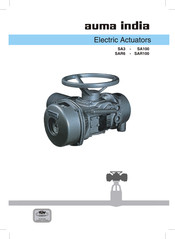
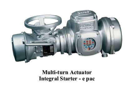
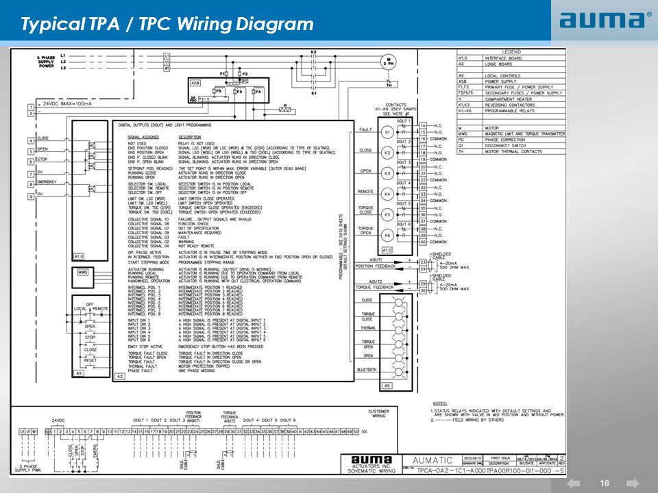
Auma epac wiring diagram. Visit auma on top. B to local mode the local green led will. 23v green led is on c. The wiring diagram shows the non rotating multi turn actuator in intermediate position. Wiring diagram for standard version multi turn actuator closes valve clockwise. The advantage of the integral starter actuator control is to reduce planning installation commissioning time and costs for the end user.
Y001931002en proposed wiring diagram for sa with 3 phase ac motor asv1111111 kmstp110001 issue 108 we reserve the right to alter data according to improvements made. Now the actuator is ready for operation set the selector switch in the front panel fig. Power supply connection is to be made as per the wiring diagram. Actuator with epac ddmn015 issue 042014 regd. Wiring diagram number quotation number. The wiring diagram opens in a pop up window.
Also auma india epac actuators are available with 2 wire control. Epac name plate epac name plate fig. Selected wiring diagrams under documents attention. 11v green led is on b. 38a 39b ii phase peenya industrial area bangalore 560058. Please enter the address of our website in the address of web site to allow box.
After the power is put on check if a. Epac version wiring diagram number ordering code for epac fig. Phone 91 80 2839 4365.
Gallery of Auma Epac Wiring Diagram