What others are saying ats panel control is the best option in situation wherever you have to control a power generator that is connected to the mains in a standby configuration. Standard diagrams transfer between 2 sources 3 bus bars comut 050 a t1 t2 q2 q4 ats q1 q3 ats cl cl ncl q5 comut 049 a t1 cl cl p1 p3 ncl p2 t2 p4 standard solution socomec solution 1 sources are 2 transformers 2 sources are 1 transformer and 1 genset comut 052 a t1 q3 q1 q2 ats ncl clcl g comut 051 a t1 p1 p3 p4 ncl p2 standard socomec.

Automatic Transferred Switch Ats Circuit Diagram
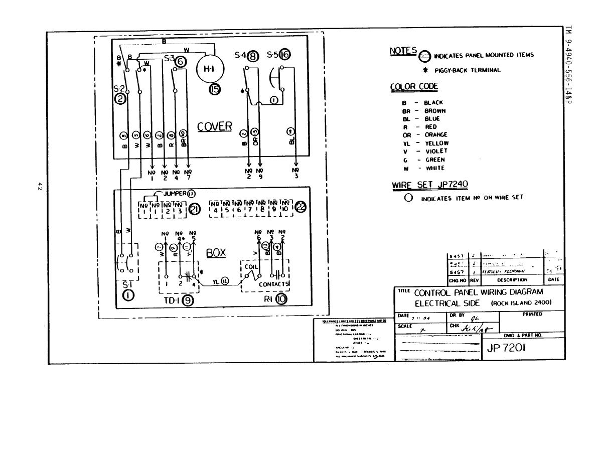
Ats wiring diagram pdf. Wiring diagram fig 1. This document contains the following wiring infonnation. Cutler hammer automatic transfer switch wiring diagrams directions for use the drawing package can be used a s a point to point wiring diagram for maintenance and diagnostic purposes for solid state logic spb transfer switches all voltages. Superior design and robust construction make jundi electrical industry teco automatic transfer switch the industry. 01 07. Ats panel wiring diagram pdf.
Ats022 selects the power supply line by acting directly on the cbs provided on the lines. The automatic transfer switch ats figure 21 and the generator transfer switch gts. Ats022 can be used with automatic cbs and abb sace switch disconnectors. Ats gts line out doc 020 161 b0 rev. 6 ats with sw1 cb1 on unit is in ups mode. Ats ups fig 2.
The automatic transfer switch ats022 is used in all installations where switching is required between two lines to ensure the supply of loads in case of a fault on one line. 12 selection the size of automatic transfer switch 13 automatic transfer switch components 14 modes of operation 15 schematic circuit diagram for automatic transfer switch 16 recommended cable size 17 specifications 171 general specification 172 controller specification 18 ordering information 19 detailed drawings. Gts fxm family fxm family fig 3.
Gallery of Ats Wiring Diagram Pdf