Exhaust fans are used to maintain the temperature of the apfc panel. The output obtained from the rectifier is a pulsating dc voltage.

How To Wire Power Factor Correction Panel
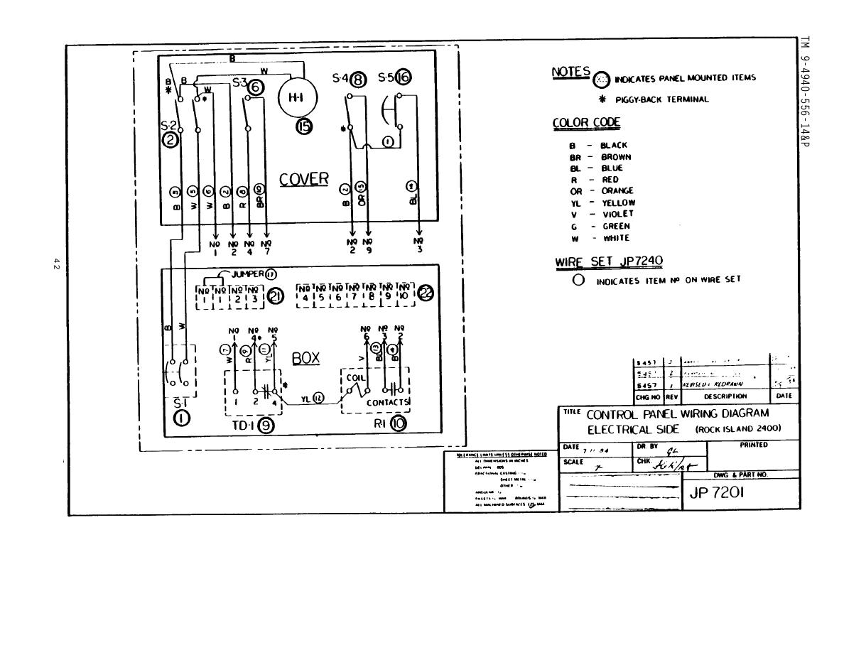
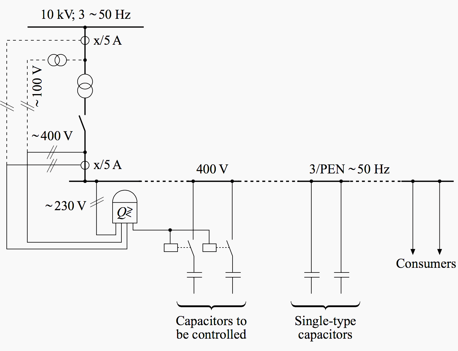
Apfc panel wiring diagram pdf. Apfc is an automatic power factor control panel which is used to improve the power factor whenever required by switching on and off the required capacitor bank units automatically. Refer fig no 3 figm. At the time of tightening screws and wiring be careful about the invasions of parings or the electric wire into the device. In performing electric wiring work. In case there is no transformer in the installation then the ct for sensing power factor should be provided at the incoming of main switch of the plant. It is used to improve power factor to meet the current requirement to reduce the billing and also to improve feeder voltage regulation.
Through the thousands of pictures on the web about relay panel wiring diagram we choices the top libraries using best quality simply for you all and now this images is actually one of images choices in your best photos gallery regarding relay panel wiring diagrami really hope you may want it. 230v from the mains is step down by transformer to12v and is fed to the rectifier. 16 tida 00737 this ti design demonstrates the working of various blocks that are typically used in the apfc in an optimized way with flexibility to expand. Final wiring diagram of the pcc mcc pdb power and control circuit with ferrules number shall be submitted along with the pccmccpdb as one of the documents. 1 200 kvar apfc panel 12 stage 200 kvar apfc panel rhom lt d sine 2 spredor link lt d sine 2 cap duty contactor lt moc 2 add on lt moc 2 on delay timer giceq 18 sec 2 lum pb tekniceq lpbo 4 capacitor bank 440vac 50 hzs mpph 10 kvar ltepcos mpph 20 e 5 kvar capacitor feeder 5 kvar 2 32a tp mccb 25 ka with tmd release lt d sine 2. Perform connection after you fully check with the connection diagram.
The apfc panel has a number of capacitor banks and busbars that carry large currents. The input to the circuit is given from the regulated power supply. Apfc stands for auto power factor correction panel. The current transformer for instrument. Fabricated from sheet steel shall be crca of minimum 20 mm thickness. The outgoing terminals and neural link shall be brought out to a cable alley suitably located and accessible from the panel front.
That photograph apfc relay control wiring diagram apfc panel wiring diagram pdf within relay panel. Specification of apfc panel design manufacturing supply installation testing and commissioning of apfc panel of 200kvar 12 stages as per following specification general the 440v apfc panel shall be metal clad indoor type floor mounted in non drawout execution. Block diagram of apfc system fig2 shows the block diagram of apfc system. Power factor is the ratio of active power to apparent power and it is a major component in measuring electrical consumption. Do not perform hot line work. Note that apfc panel can maintain the power factor on lt side of transformer and it is necessary to provide fix compensation for power transformer refer fig no 1 5.
The ac input ie. It can cause electrification device failure or fire.
Gallery of Apfc Panel Wiring Diagram Pdf