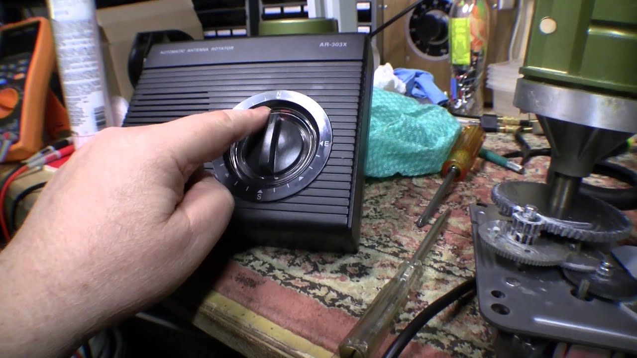
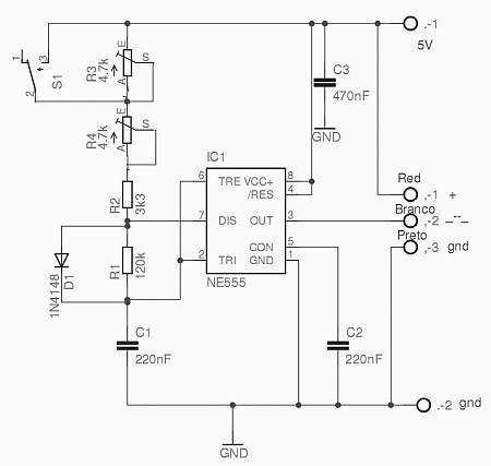
The theory of operation concerns two separate circuits. Controller unit new features in the ham iv include an 8 pin.

Alliance Wiring Diagram Wiring Diagram
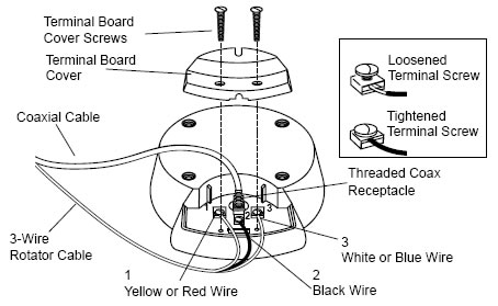
Antenna rotor wiring diagram. The control unit mus be placed inside the house or other protected location. All channel master antenna rotors use 3 conductor rotor wire. The rotor wire as shown. 15 complete routing of the antenna lead wire and rotor wire to the tv set per antenna manufacturers instruc tions. Control unit rotator wire not included unidad de control el cable del rotor no está incluido unité de contrôle fil du rotor non inclus 3. Facilitate mounting the ham iv rotator on top of a mast.
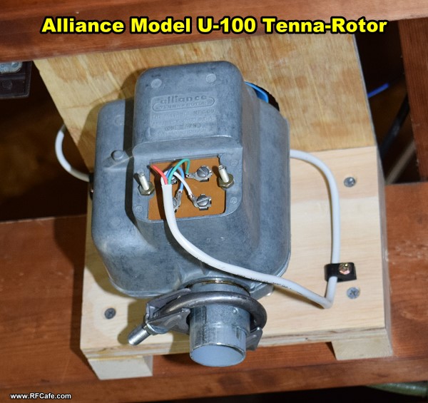
A owners manual pin 51563 10. The rotor unit which mounts on the mast below the antenna and the control box which is placed on or about the tv receiverthese are interconnected by a four or five conductor cable. The rotator unit must be wired to the control unit with an 8 wire cable. Remove the bottom or access plate of the drive unit housing and attach the rotor wires. The alliance tenna rotor consists of two units. Antenna masts coaxial cable and rotator cable figure 2 figure 3 2.
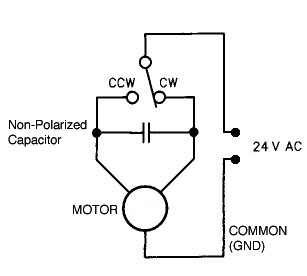
For runs up to 200ft you can use 22ga 3 conductor wire. Drive unit unidad de manejo unité dentraînement 2. Continue to use separate stand offs for anten na wire and rotor wire. The rotator unit must be wi red to the controlunit with an 8 wire cable. The first is the power circuit which in all tenna rotors transmits the power that actuates the motor. Look in you instruction manual to see what wire size to use for longer runs.
Remote control control remoto. Most rotor wire will be color coded. Control box installation s tep a. Lower mast support antenna size is restricted to 75 square feet of wind surface area. Included in the shipping box are. Stanoff antenna wire slack antenna lejowiae step 11 f ig.
The control unit must be placed inside the house or other protected location. Included in the rotor are.
Gallery of Antenna Rotor Wiring Diagram