1 antenna layout showing the placement of the ais related antennas with respect to the others. Abs electrical schematic lx ex 2005 fig.

Bluetooth Pilot Interface Operation Manual Pdf Free Download
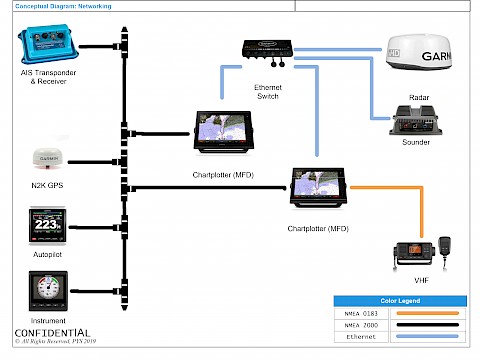
Ais pilot plug wiring diagram. 43 mount the ais alarm unit 18 44 mount external pilot plug optional 19. The ais 300 wiring layout diagram on page 2 contains an example of the ais 300 connected to a garmin chartplotter through a nmea 2000 network. The instructions given here are specific to the mcmurdo m 1 but by following the principle and the named connections it should be possible to install this accessory. Ais pilot plug wifi ksn11 w polarity auto corrector click here for manuals download click here for video show this is the light. In some cases a reboot may be necessary if there are driver conflicts or other issues. If the ais data cable has a de 9 connector see de 9 connection.
Required supplies not included. Streetpilot iii gps iiiiiv comparable to garmin ga 26c remote antenna it is an icom m ais and after checking the specs right now it can. If the ais data cable has bare wires for the connection see bare wire connection. De 9 connection if the ais equipment includes a data cable with a de 9 connector use the instructions in this section. At gear position indicator electrical schematic 2005 fig. There should be the following documentation for a new ais installation.
Pilot plug assembly 89 081 wiring instructions the pilot plug assembly is supplied already wired to a 20 m cable. Verification that interface testing was successfully completed. Icom m506 to pilot plug wiring diagram is there a simple plug and play gps antenna that will function properly. At electronic controls system electrical schematic 2005 fig. A list of all barrier strips t connectors and terminations that identifies their physical location aboard the vessel. This means you can only run one program at a.
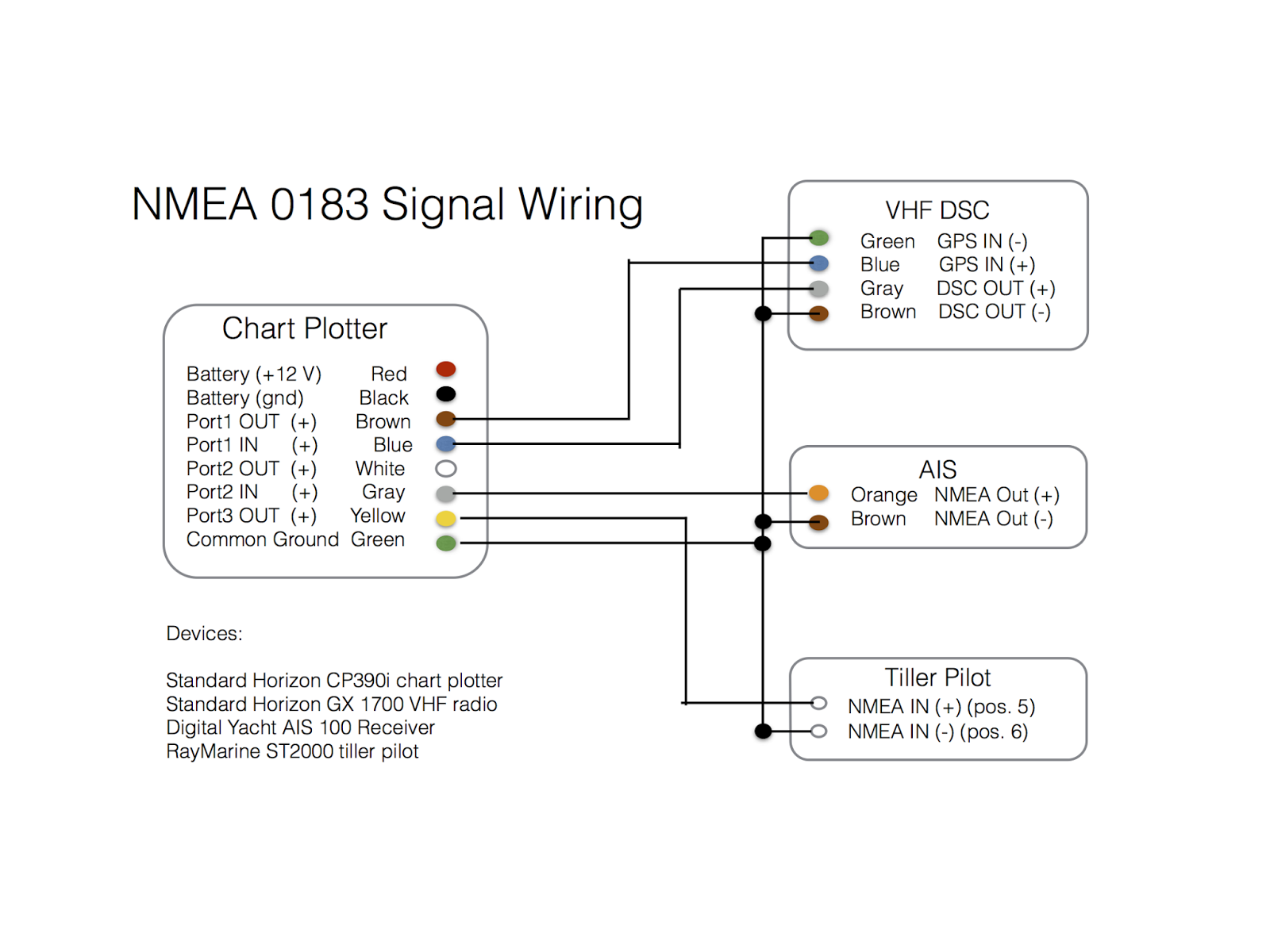
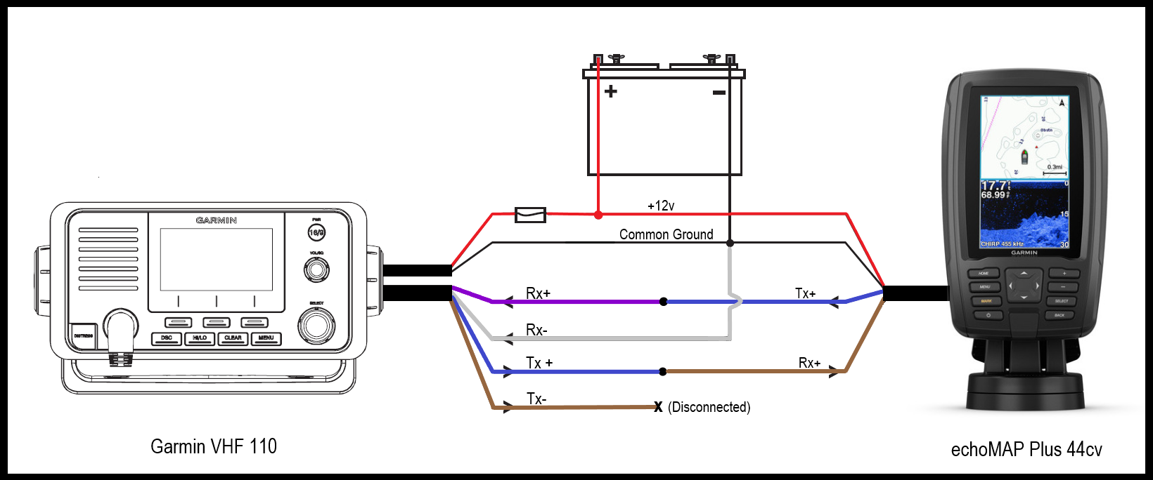
Windows only allows one process to access a com port device including virtual com port usb devices at a time. Accessory power socket electrical schematic 2005. If you are unfamiliar with nmea 2000 see the nmea 2000 network fundamentals chapter in the technical reference for. The free end of this cable is to be connected to the ais system. Connection of external pilot plug 20 figure 5 1. 82 nmea 0183 wiring requirements.
Humminbird pc connect cable as pc2 ais. Access our free wiring diagrams repair guide for honda pilot 2003 2005 through autozone rewards. Intended data flow showing input and output ports. External pilot plug 19 figure 4 16. Wiring diagram for r4 display 25 figure 5 2. When this is complete plug in the usb ais device to see whether it is now installed correctly.
Connecting the common signal ground c wires of the ecdis port 26. 2 ais arrangement in the pilothouse showing component locations 3 a one line block diagram showing the ais its power supplys pilot plug antennas. Alarm relay wiring 18 figure 4 15.
Gallery of Ais Pilot Plug Wiring Diagram