Also see connection diagrams vertical e clipse bypass page 91. Diagnostics and maintenance 10.
Abb Drive Ach550 Wiring Diagram Abb Drive Ach550 Wiring
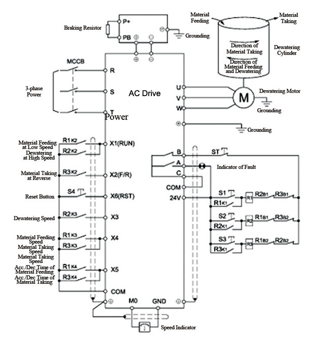
Ach550 wiring diagram. Bp0056 ach550 input power ground lug. Abb ach550 wiring diagram sample abb vfd wiring diagram demag crane free image about with overhead. Connection diagrams standard e bypass r7r8 floor mounted ach550 standard e bypass units are configured for wiring access from the top. Ach550 there may be dangerous voltage from external sources on the terminals of the relay outputs. Never connect line voltage to drive output terminals t1 t2 and t3. Check installation check installation on page 1 27.
Collection of abb ach550 wiring diagram. The terminal layout for r7r8. The r5r6 power and ground terminals. Install wiring wiring overview on page 1 18 and install the wiring on page 1 23. A wiring diagram is a simplified conventional photographic representation of an electric circuit. Refer to the ach550 uh users manual for control connections to the drive.
8 ach550 installation operation and maintenance manual ach550 uh connection diagrams the following diagrams show. Reinstall the cover re install cover on page 1 27. Do not connect or disconnect input or output power wiring or control wires when power is applied. The following figure shows the standard e bypass floor mounted wiring connection points. Do not make any voltage tolerance tests hi pot or megger on any part of the unit. Interconnecting wire paths may be revealed about where particular receptacles or fixtures should get on a common circuit.
Page 99 ach580 installation operation and maintenance manual install the control wiring connect control wiring to terminal block x1 on the ach580 control board and to terminal block x2 on the e clipse bypass control board. Abb 150 wiring diagrams wiring auto wiring diagrams instructions. Ach550 01 users manual 3afe68258537 english hvac info guide 3afe68338743 english flange mounting instructions option manuals. Application macros and wiring 6. Wiring overview connection diagrams standard drive with input disconnect wall mounted the following figure shows the standard drive with input disconnect wall mounted wiring connection points. Abb vfd wiring diagram.
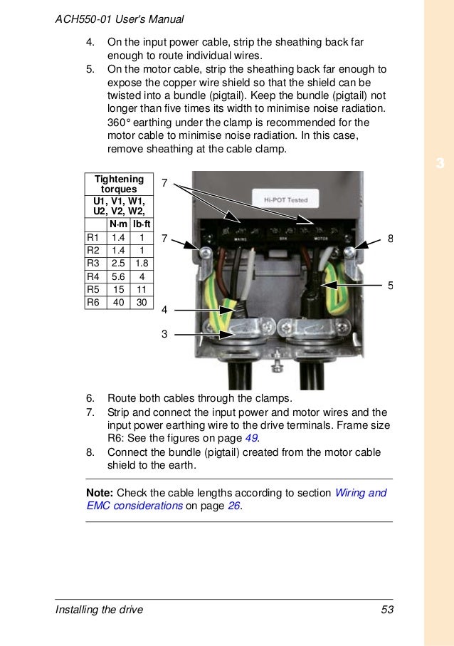
It shows the parts of the circuit as streamlined forms and the power and also signal links in between the tools. Abb ach550 wiring diagram building circuitry representations show the approximate places and also interconnections of receptacles illumination and also irreversible electrical services in a structure. Real time clock and timed functions 7. The terminal layout for frame size r3 which in general applies to frame sizes r1r6 except for the r5r6 power and ground terminals. Parameter listing and descriptions 9. Installing the wiring supplement to ach550 uh users manual warning.
For more information on these connections refer to the. Ach550 input power terminals motor terminals ground lugs. Abb vfd wiring diagram demag crane free image about with overhead. Refer to the ach550 uh users manual page 1 317 for control connections to the drive.
Gallery of Ach550 Wiring Diagram