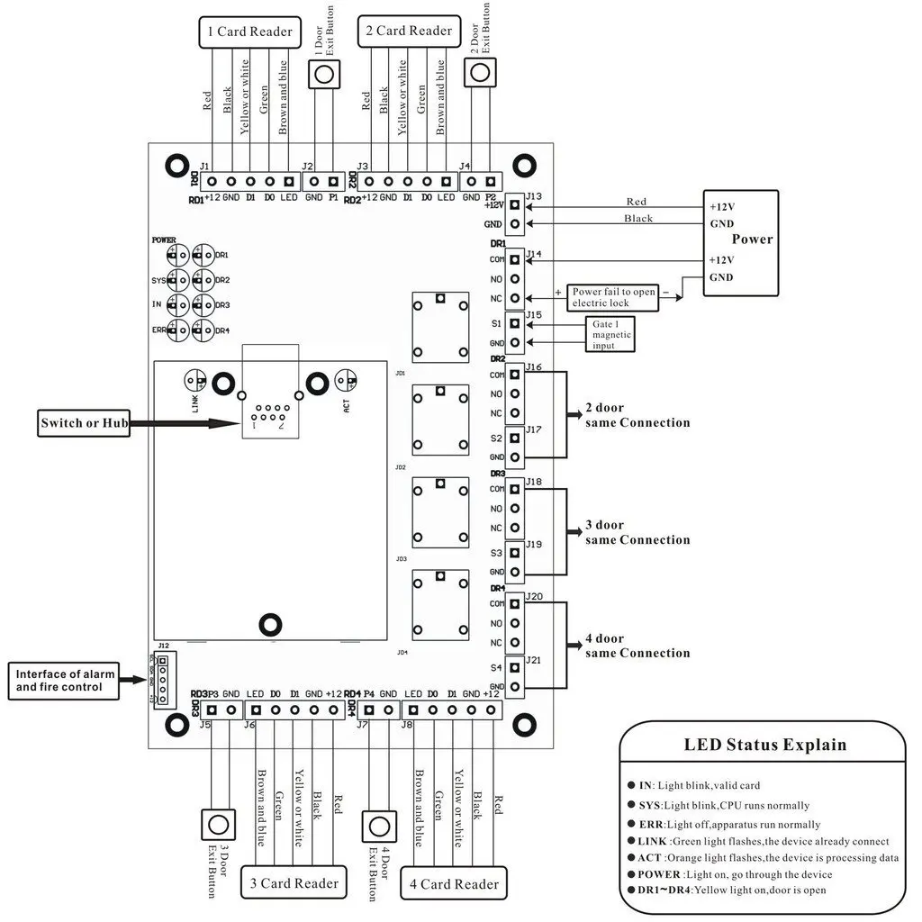
Wiring diagram for acb t01 single door access control board 1 card reader in red black yellow white green brown and blue 12 gnd d1 d0 led 12 gnd d1 d0 led gnd p1. Typical starter wiring diagram three phase.
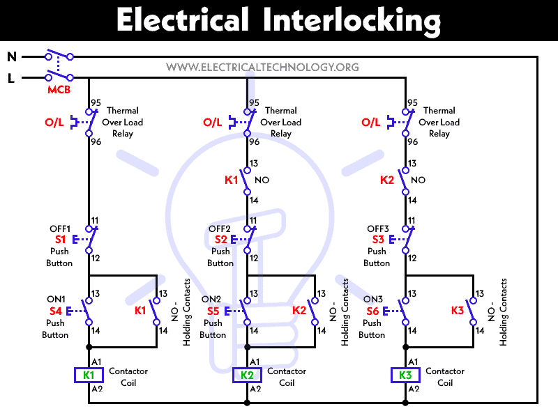
What Is Electrical Interlocking Power Amp Control Diagrams
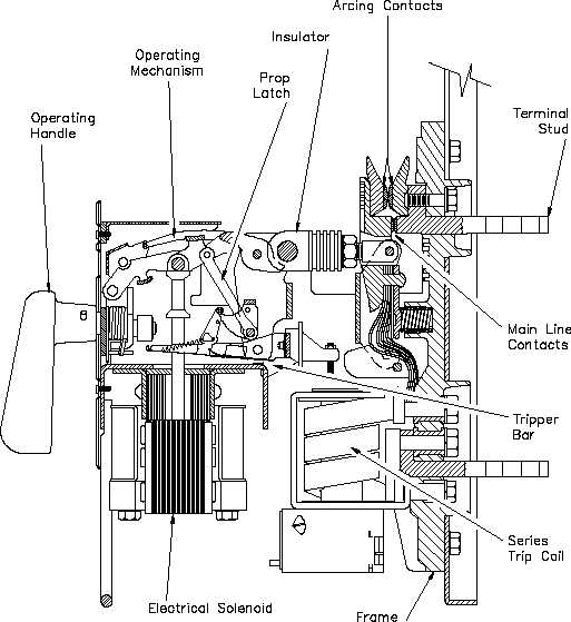
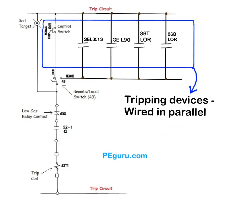
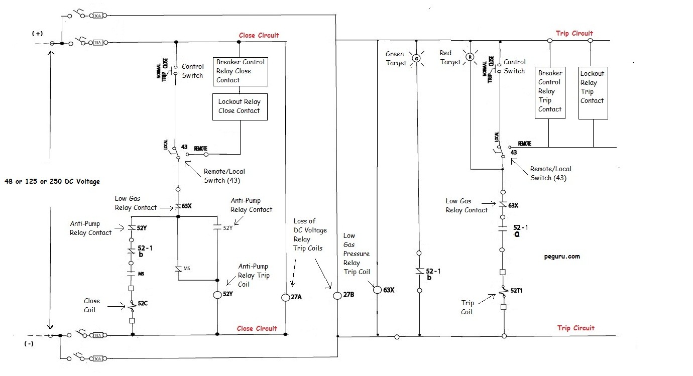
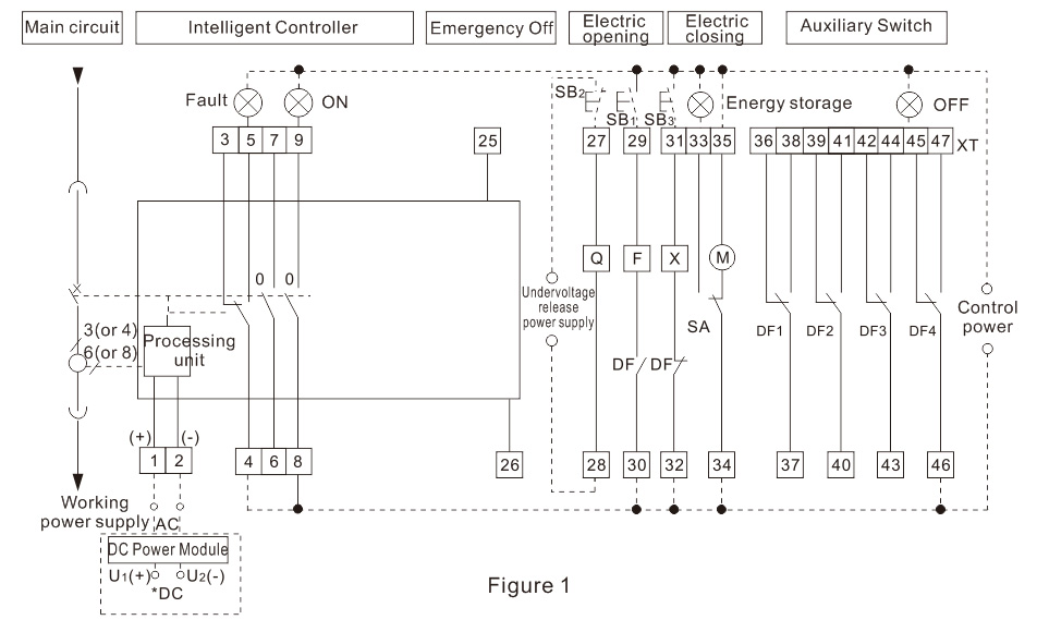
Acb control wiring diagram. It will not allow to both relays to be in a closed position. D latch of the mechanism spring not. From acb but trip bar of release kept free. The control circuit may not be at the same voltage as the power circuit. In the automatic changeover switch for generator circuit diagram the contactors are indicated kg for generator and km for mains. The control circuit is separate from the motor circuit.
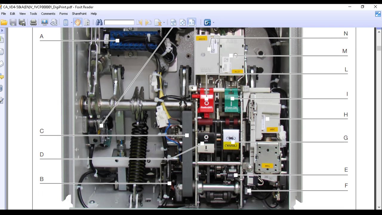
B check control wiring. Internal wiring diagram of new dn release ct r phase ct y phase ct b phase t1 m1 t2 m2 t1 m1 t2 m2 t2 m1 t2 m2 s o l. It operates in air where air blast as an arc quenching medium at atmospheric pressure to protect the connected electric circuits. Check control wiring of shunt release ensure that shunt release gets supply. This guide will help you to make by your own generator control panels for standby generator. Three phase motor power control wiring diagrams 3 phase motor power control wiring diagrams three phase motor connection schematic power and control.
2 incomer one buscoupler. Send me acb buscoupler control wiring with using under voltage coil. Air circuit breaker acb air circuit breaker acb is an electrical protection device used for short circuit and overcurrent protection up to 15kv with amperes rating of 800a to 10ka. If the volt ages are different it is called separate control. When the voltage of the control and power circuits is the same it is referred to as common control.
Gallery of Acb Control Wiring Diagram