Point io cold junction compensation wiring base assembly 1734 in583 point io wiring base assembly point io wiring base assembly installation instructions 1734 in013. The adapter provides an interface for controlling and communicating with point io modules from an ethernetip network.

Use Of Etap In Switch Based Ring Network Plc
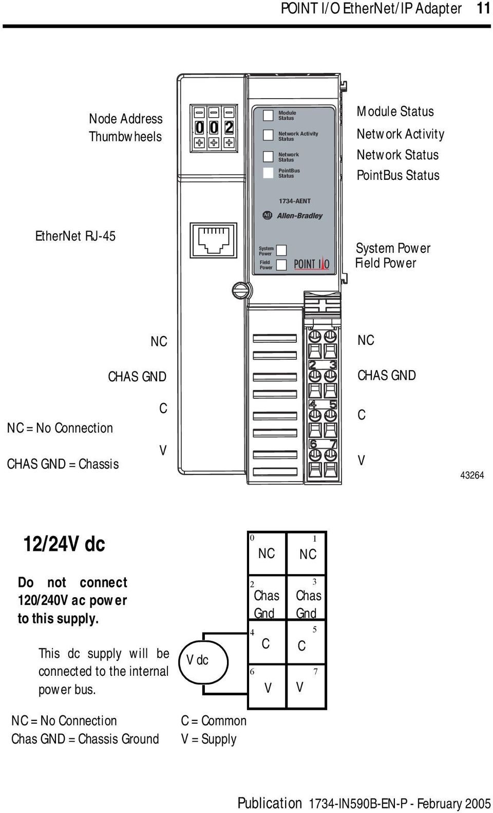
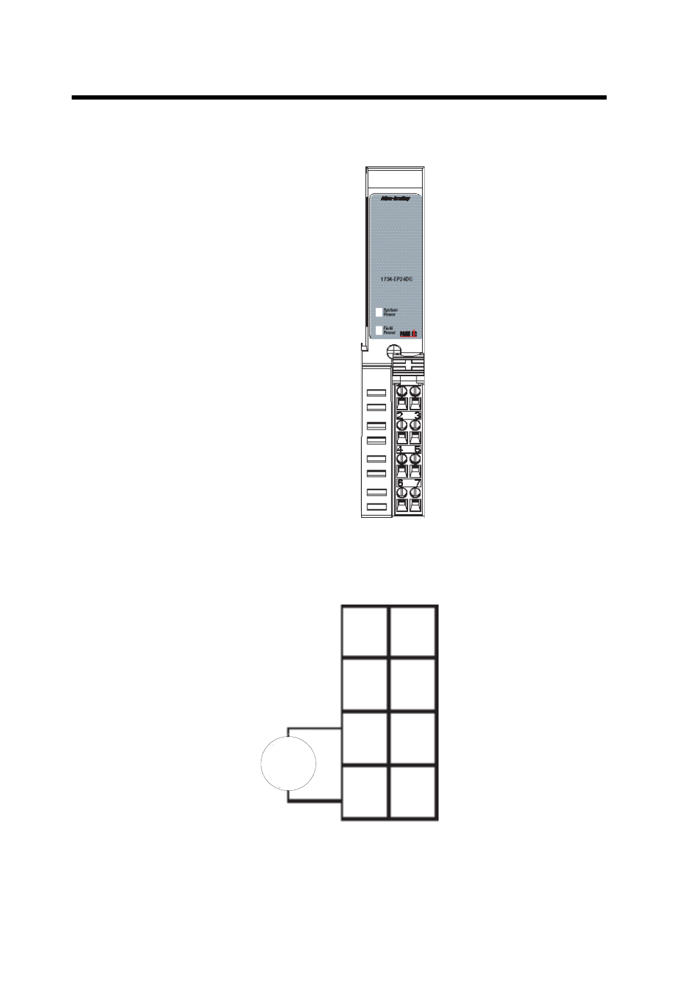
1734 aent wiring diagram. The 1734 aentr adapters will accept io connections with the electronic keying for the 1734 aent. No patent liability is assumed by rockwell automation inc. Wiring diagram ie8c. Catalog number 1734 aent user manual. 1734 point io ethernetip adapter interpret status indicators refer to the following diagram and table. 1734 aentr wiring diagram 29112018 29112018 6 comments on 1734 aentr wiring diagram aent aentr aentr aent comm e the examples and diagrams in this manual are included solely for illustrative purposes.
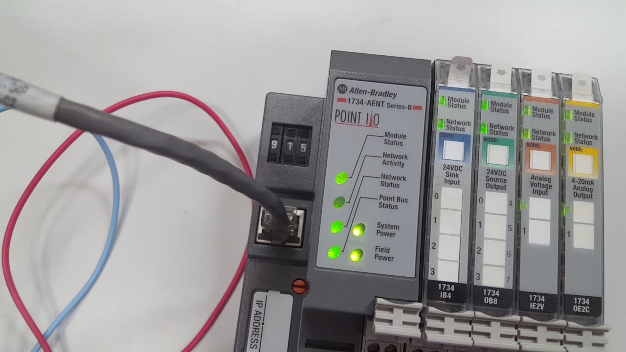
Allen bradley 1734 aentr wiring diagram the examples and diagrams in this manual are included solely for illustrative allen bradley rockwell automation armorpoint controllogix logix. Ow4 wiring tb mb ow4 wiring diagram ib8s ie8c wiring connections ow4wiring ow4 ep24dc text. This manual is a reference guide for the aentr aentr series b. 1734 aent adapter description description. Wiring base assembly is the 1734 tb or 1734 tbs point io two piece terminal base which includes the 1734 rtb or 1734 rtbs removable terminal block and 1734 mb. Publication 1734 in590c en p december 2018 about the adapter the 1734 aent point io ethernetip adapter is a communications adapter for point io modules.
We assume you have a good understanding of ethernet and the tcpip protocol. 1734 aent adapter pdf manual download. 1734 in583 point io wiring base assembly point io wiring base assembly installation instructions 1734 in013. Because of the. View and download allen bradley 1734 aent installation instructions manual online. Installation instructions point io 2 and 4 relay output modules catalog numbers ow2 successful application and understanding of the product.
Rslogix 5000 version 17 or greater must be used for the 1734 aentr add on profile. Noting that this end has a curved section that engages with the wiring base. Communicates with point io through a 1734 aent adapter. With respect to use of information circuits equipment or software described in this. The examples and diagrams in this manual are included solely for illustrative purposes. Wiring diagram module locking mechanism io module wiring base rtb rtb removal handle din rail locking screw orange 2 point io publication 1734 in510b en p august 2000 wiring diagrams v dc nc c v nc chass gnd c v daisy chain power out to modules 1224v dc power nc no connection chass gnd chassis ground c common v supply.
1734 point io ethernetip adapter. This allows the 1734 aentr adapter to be used in a daisy chain topology with the 1734 aent profile used for the 1734 aentr.
Gallery of 1734 Aent Wiring Diagram