The wiu 4 also bridges common wiring connections for junction box designs. Wiu 4 to micro5 8rp board.

Exhibit1012300orchardsub
Wiu 2 wiring diagram. Microcontroller the wiu 4 can be configured with a micropx 2000 or micropxn 2000. Schlage electronics schlage ad400 wiring diagram utc casi micro px 2000 wiu 2 wiegand wiring diagrams. Each step is explained in further detail in the sections that follow. Er 1 2 4 5. Horizontalvertical mount 2 w 325 deep 826mm wiu 2w weatherproof covers for locking and straight blade receptacles metal weatherbox while in use weather protective covers extra duty while in use weather protective covers product description 1 gang extra duty self closing 2 gang extra duty self closing weatherproof while in use covers. 108 to 132 vdc 350 ma maximum mr50 power.
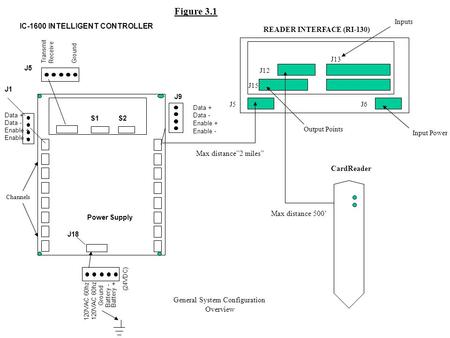
12 vdc 300 ma maximum per port communication. Door contact request to exit door strike and alarm shunt outputs are all supported by the wiu 4. Wiu 4 to micropx 2000 pxn 2000 or m2000pxnplus interface wiegand interface unit four state wiu 4 installation manual figure 5. 20 awg 500 feet maximum mr50 powered by m5 mux8. These diagrams mainly apply to external rotor motorsbut some standard frame induction motor diagrams have been included for ease of presentation. When installing the wiegand interface unit 4.
The wiu 4 must be mounted indoors in a protective enclosure or standard 2 gang electrical box installer supplied as shown in figure 1. Unit operation the wiu 4 works with current microcontroller firmware versions. Pgs ocdedv gamma series d 1417 diags. Refer to mounting the wiu 4 on page 7. These diagrams are current at the time of publication check the wiring diagram supplied with the motor. Wiring diagrams connecting the wiu 4 wiring diagrams figure 4.
24 awg 4000 feet max twisted shielded pair 120 ohm impedance mr50 power wiring. Always use wiring diagram supplied on motor nameplate. The maximum cabling distance of 1000 ft 3048 meters is influenced by wire gauge reader power requirements and the 12 vdc level from the controller. Connecting the wiu 2 wiegand interface unit two state wiu 2 installation manual connecting the wiu 2 connect the wiu 2 between the ge controller and access control reader as indicated in figure it is important to ensure all connections are made prior to applying power. Asynchronous 300 1200 2400 4800 9600 19200 or 38400 bps wiring. Open the pdf directly.
Gallery of Wiu 2 Wiring Diagram