Enc cwc ckc vcc gnd. E n e c w e c k e v c c g n d.

4 Wire Pc Fan
Vcc 20 p wiring diagram. A axis wiring diagram cp w e nv g d vcc v pos gnd. The ademco vista 20p diagram inside the lid indicates the standard colors for each screw terminal making things easy. H g 0 7 s o r e h g 0 8. Vcc is the power input of a device. This other supply pin is labeled svcc which i guess is intended to mean signal vcc or signal supply btw these pins are given their funny names on page 2 of the data sheet in the table labeled pin definitions. Gnd is normally at 0 zero volts or.
How to read the wiring diagrams wire colour codes a 9 wire colour codes wire colours are identified by the follow colour codes. Red red blu i blue yel yellow blk black wht white brn brown org orange grn green 5v 5 v. 55v vcc gnd 5v 5v 5v. This option simplifies wiring and cleans up the panel a bit. Code wire colour code wire colour b black p pink br brown r red g green sb sky blue gr gray si silver l blue v violet lg light green w white o orange y yellow if a cable has two colours the first of the two colour code. The vcc 20 p pump has been evaluated in accordance with ul2043 standard and it was found compliant with the standards requirements.
The vcc 20 p pump has individual power conductors for making a hardwire connection to the power supply. Vcc is the higher voltage with respect to gnd ground. Also if you look at page 8 of the data sheet at the diagram labeled 4. If you read a schematic diagram especially the ic pins you will notice that there are certain pins that we do not really know what it stand for. It does not have a power cord or electrical plug. It may be positive or negative with respect to gnd but most of the world runs on positive voltages like in a vehicle.
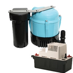
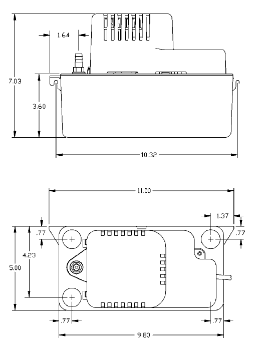
Little giant 554220101 vcc 20 p low profile plenum rated condensate pump 115v overview designed for automatic collection and removal of condensate from air conditioning refrigeration and dehumidification equipment installed in air handling and plenum applications having limited space and where gravity drainage is not possible or practical. Basic plain track wiring for dcc track feeders 20 24 gauge stranded track bus wires. End cwd ckd vcc gnd. Vcc collector supply voltage vee emitter supply vbb base supply voltage vdd drain supply vss source supply. Ena cwa cka vcc gnd. Engineering data specifications replacement parts item part number tank 154004 impeller 154009 volute 154015 cover motor 154006 check valve 154715 switch pump 950337 seal ring 928006 safety switch 154714 floatstem 154017 adapter 14 154037 head meters flow litershour head feet.
Solder rail joints between feeders andor at. Telephone wiring terminals 21 24. Drive output circuit you can see what pvcc the motor. 10 gauge 14 gauge solid conduit wire 14 gauge more than sufficient for 100 feet run in ho 3 feet ok between feeds closer on smaller code track. Connect the flying leads of an rj 31x cord to the terminals as shown. They are all supply voltages.
Gallery of Vcc 20 P Wiring Diagram