If you wire it to power from b1 on the aquastat instead of from the output on the cad cell this may help. If proper clearances cannot be maintained from combustible material type b vent pipe should be.

Roberts Gordon 90707501k Power Vent Assembly
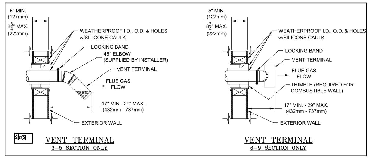
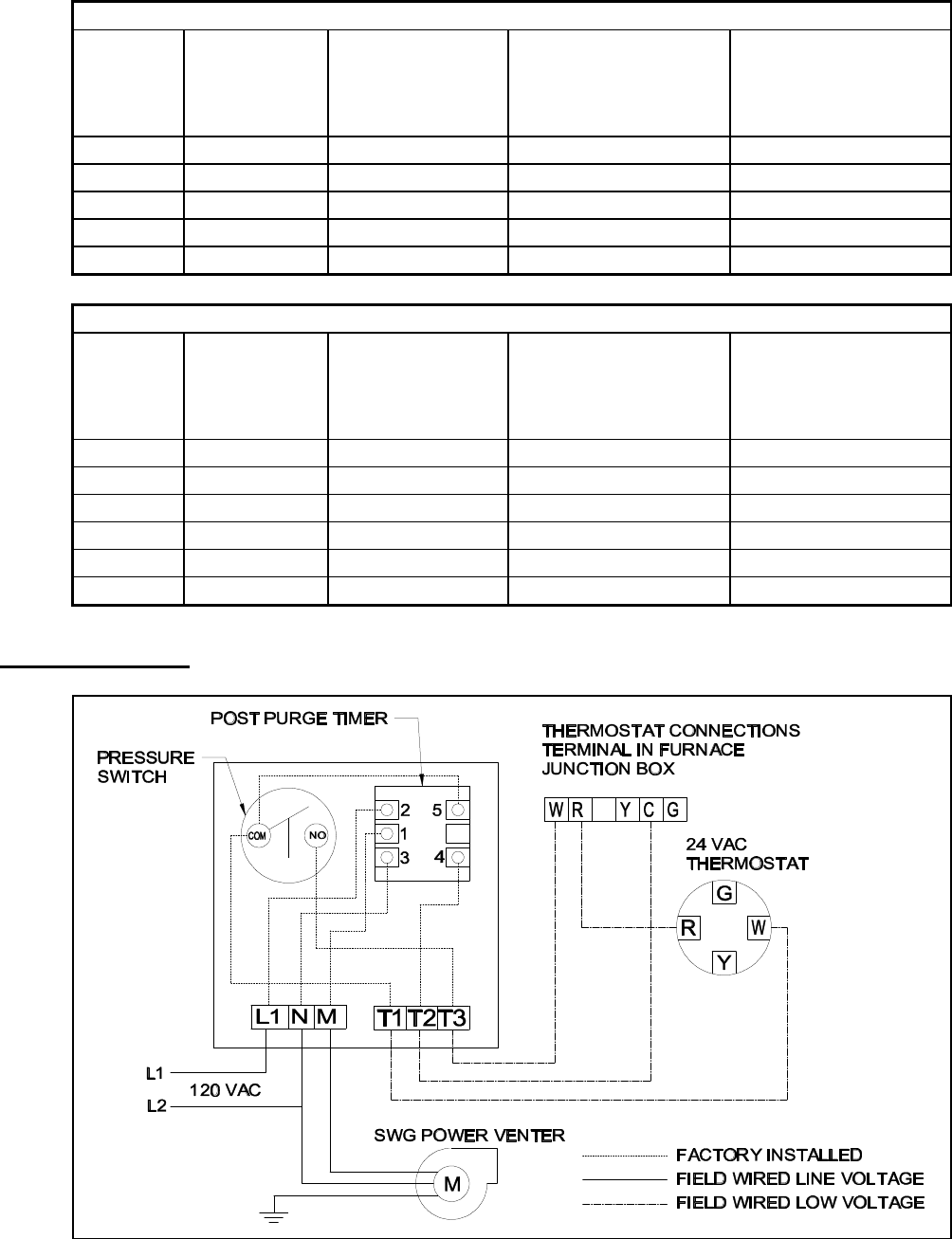
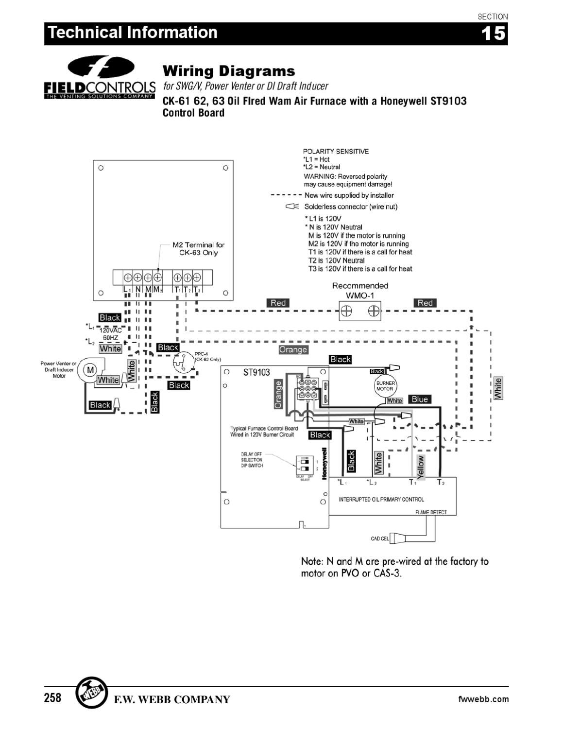
Swg power vent wiring diagram. After determining the location of the venting system termination point see diagram a cut a square hole through the wall 1 larger than the outer pipe diameter of the power venter. 100 negative pressure in the vent pipe for maximum safety. Mount the power venter through the wall keeping the outer pipe centered in the hole. Gsk 3 spill switch installation manual. The swg mounts on the outside of the building and pulls the combustion gas from the appliance through the outside wall utilizing 100 negative pressure. I always wonder about 2 things when wiring this power venter or any combustion air system for oil in this example.
See figure 4 2. Route the tubing to the ck 61. Single wall vent pipe refer to diagram b may be used to join an appliance to the venting system but if. Attach the vent pipe over the crimped. Swg swg stainless series patented. This equipment is designed to overcome minor.
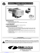
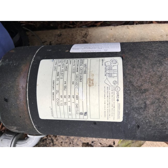
Sidewall power venter kit model. Tems included in kit 1 junction box with mounted pressure switch and solid state post purge control 1 2 ft. Power vent i would check the wiring. Benefits of the swg power venter include. See figure 3 2. Connect the supplied 14 aluminum tubing to the tubing connector.
Connecting power venter to appliance figure 3 figure 4 diagram a 3. Disconnect power supply before making wiring connections to prevent electrical shock and equipment damage. Why does the signal come from. With some of the new prepost purge controls you can get bleed by voltage that will turn the power vent on without the burner. Page 1 120 vac system control kit model. Ck 61 designed for use on swg series power vent hoods for controlling oil fired heating appliances with 120 vac controls.
Single wall vent pipe refer to diagram b may be used to join the appliance to the power venter. Mounting location on an mg 1 4 9 barometric draft control. Attach the 14 inch tubing connector to the pressure tube on the swg venter. Installation manual and wiring diagram for model swg 4l power venter for lennox g23 g24m and 80mgf series units. Pressure switch sensing tube installation 1. Looking at the diagram.
The swg combines the motor blower and vent hood in one complete easy to install unit. The burner motor on the primary to the pv control then back to the burner motor instead of just directly from the high limit b1 on aquastat. Installation manual for model gsk 3 spill switch. Concealed wiring or plumbing inside walls. The swg power venter approximately 1 long. Electrical power supply to the appliance when wiring the blocked vent switch.
Replaced 15 year old field swg 4 power venter with new one had a problem with old control not working right had to fix for safety reasons cleaned oil fired.
Gallery of Swg Power Vent Wiring Diagram