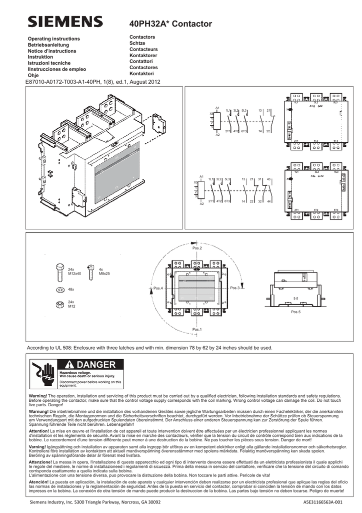
Wiring diagrams 20 amp class clm mechanically held lighting heating contactor 20 amp 24306100401 sheet 1 aux. Therefore use a single.

Control Products Nema Amp General Purpose Controls Pdf Free
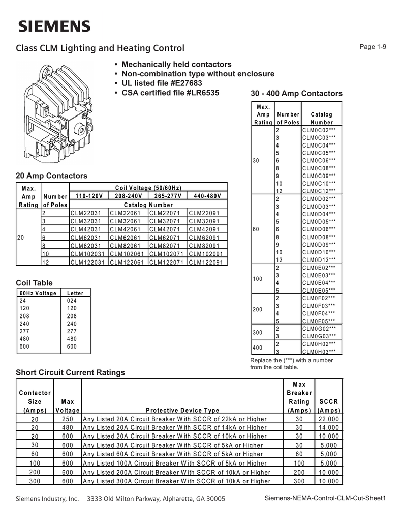
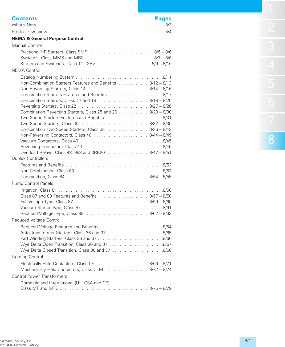
Siemens clm lighting contactor wiring diagram. Magnetically latched clm lighting and heating contactors can control tungsten fluorescent and metal vapor lamp or heating. Class lc electrically held lighting contactors convertible to mechanically held features 8 catalog numbering system 9 selection 10 11 technical data 12 accessories factory mods and replacement parts 13 16 dimensions 17 21 wiring diagrams 22 24 contents class clm mechanically held lighting contactors are. Class le electrically held lighting contactors 4 class lc electrically held lighting contactors 5 convertible to mechanically held class clm magnetically and mechanically held lighting contactors 6. Electrically held contactors siemens contactor type clm. Siemens industry catalog low voltage controls and distribution nema general purpose controls lighting control mechanically held contactors class clm cm. Wiring control modules for 20a clm lighting contactors security information in order to protect technical infrastructures systems machines and networks against cyber threats it is necessary to implement and continuously maintain a holistic state of the art it security.
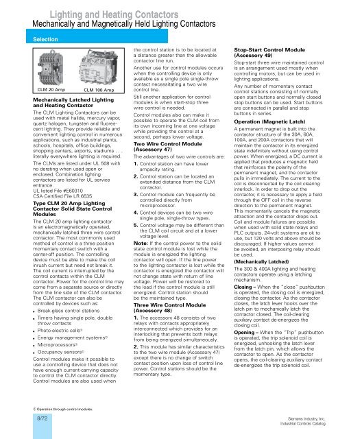
This should now open when light close when dark. One type of contactor is an electrically held contactor which is similar to a magnetic starter. If neither or both terminals are energized no output will occur. One terminal must be energized to close the contactor. Break your circuit l n e through your contactor. Clm437978 accessory 48 control modules are for three wire control of the clm contactor.
All control wiring for contactor operation must only be made to. Siemens class clm cm magnetically and mechanically held lighting contactors are used in applications where it is critical that the contacts remain in the closed position during loss of control power. Another terminal must be energized to open the contactor. A detailed wiring diagram is available on the siemens website at. 5300 triangle parkway norcross ga 30092 a5e31166447a 002. These contactors do not change state and disconnect power from the load during a loss of control power whether momentary or sustained.
Contact when used 1 6 coil l o c contactor control voltage l 5 7 1 2 3 4 5 o c 12 reference number denote pole location refer to chart load line black no orange nc brown control module voltage remote control module when used see fig. As an already registered user simply enter your userame and password in the login page in the appropriate fields. Link a permanent live and a neutral from your supply to your coil al a2 then use your switch feed to your photocell from a1 and switch the wire to the switched phase of your contactor load. Most lighting and heating applications require a contactor to control the loads. Siemens comprehensive line of lighting contactors offer a wide range of control solutions for lighting applications.
Gallery of Siemens Clm Lighting Contactor Wiring Diagram