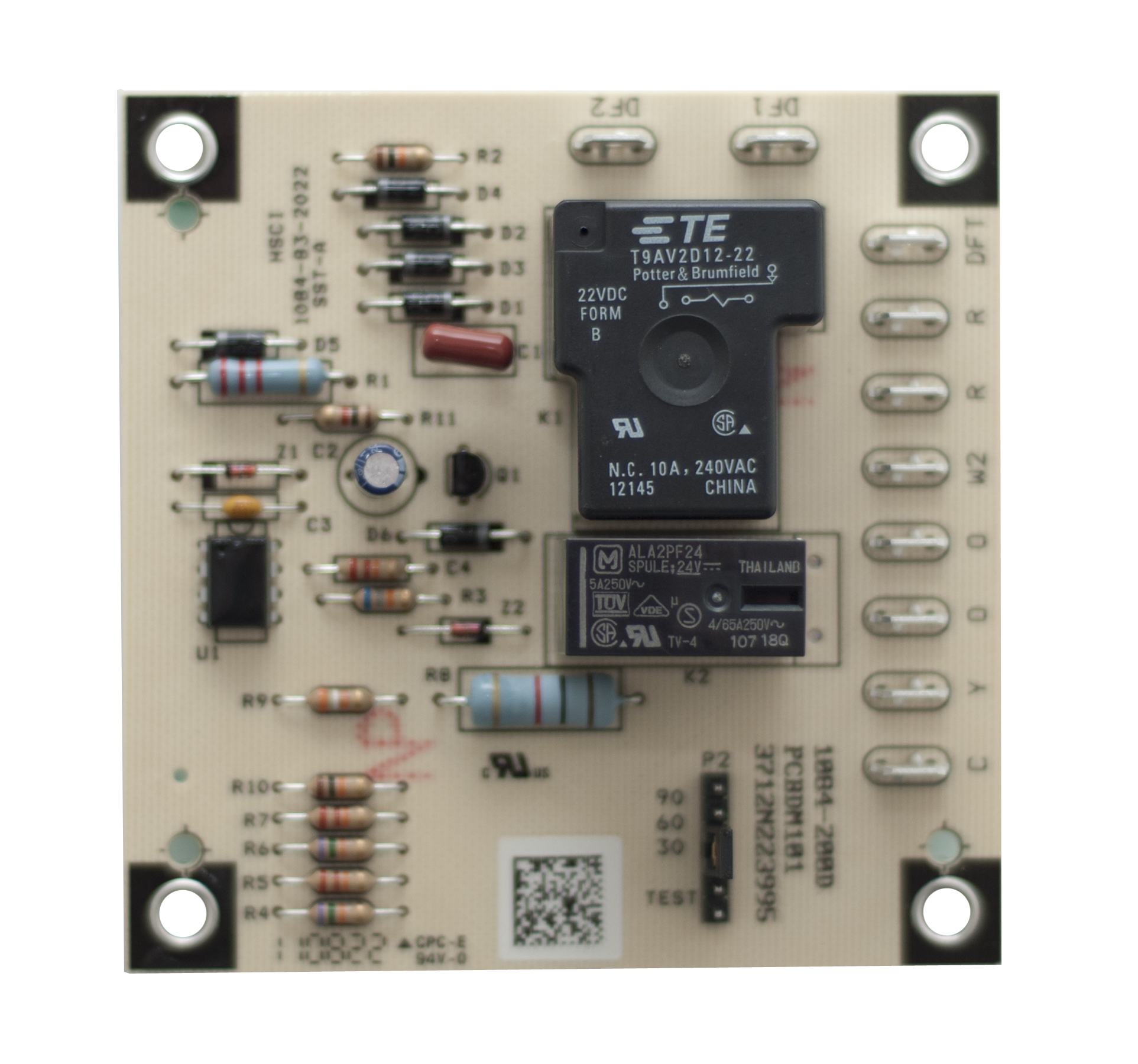
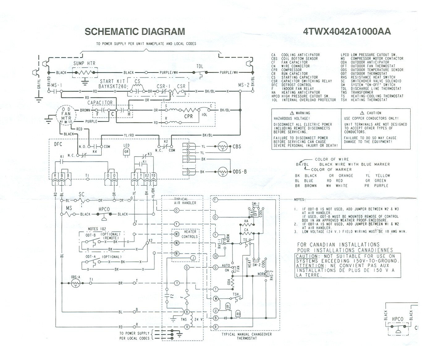
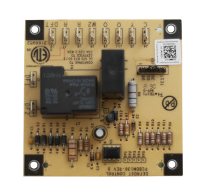
Connection diagram o bl o bl attach ground ps2 ps1 lphp lphp two switch wiring r power supply per nec. This pcbdm101s defrost control board is a guaranteed genuine goodman oem replacement circuit control board for several goodman amana and janitrol units.

0c4 Goodman Air Handler Control Board Wiring Diagrams With
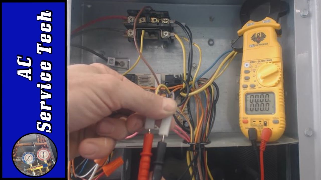
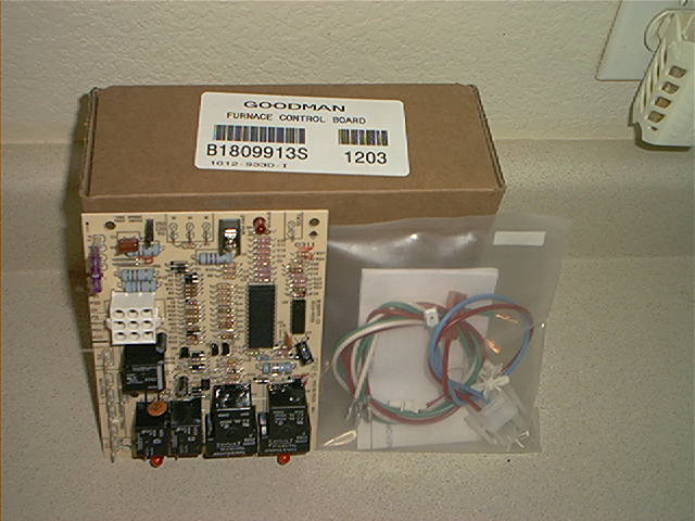
Pcbdm101s wiring diagram. Icm controls icm318 defrost control goodman b1226008 icm w1001 4 41. How to know if your heat pump defrost board is working properly so that it wont freeze up. Furnace control board wiring diagram elegant goodman heat pump. This is a brand new oem goodmanamanajanitrol heat pump defrost control circuit board the part is pcbdm133 also pcbdm133s. And local codes 208230 vac 60 hz 3 ph. With johnstone you can stay current on product and technology changes in addition to programs that make it easy for the contractor.
All of our parts are shipped factory direct giving you the assurance you need for a quality repair on your furnace air conditioning condensing unit heat pump or other goodman product. I show you how to connect thermostat wire connectors to the heat pump. Oem upgraded replacement for goodman heat pump defrost control circuit board pcbdm101s 45 out of 5 stars 17. Wiring diagram split system heat pump new goodman gas pack wiring. Also look up the data sheet for an icm 314 a third party clone of this board. Page 181 wiring diagrams ash13018 601a wiring is subject to change always refer to the wiring diagram on the unit for the most up to date wiring.
It has a simplified wiring diagram that shows exactly how everything connects. Pcbdm160 pcbdm160spartial list of goodmanjanitrolamana heat. Goodman does not assume any responsibility for property damage or personal injury june. Bk bl bl bl when used pri trans sec r bl g r bl t1 l1 cont. Page 182 service manual. I recommend downloading the technical or specification manual for an r410 ssz14 and the r22 gsh13 heat pump so you can compare the wiring diagrams for the old and new defrost control boards.
Johnstone supply is a leading wholesale distributor for multiple leading brands of hvacr equipment parts and supplies available and in stock at local branches. T t3 compressor contactor l3 ladder diagram fan y rv rv rv coil cc c defrost control. 1 wiring diagram model sizes 1 12 5 tons 208230 1. Ground equipment per nec. 2 rvs dts yel pnk speed up brnyel dft c y o w2 r e l g terminal block indoor unit red wht orn yel blk cb c y o w2 r e l w3 g blu pnk yelblu yelblu hps lps logic logic t2 cont c ctd t1 c y y dft dft rvs c r w2 o o schematic diagram ladder form. Thanks for looking and good luckoem replacement for old part s.
Goodman 0130m00105 defrost thermostat 47 out of 5 stars 21. York hvac wiring diagrams simple electronic circuits. Goodman defrost board wiring diagram collections of goodman defrost board wiring diagram for 133 wire center. 1 this manual is to be used by qualified hvac technicians only.
Gallery of Pcbdm101s Wiring Diagram