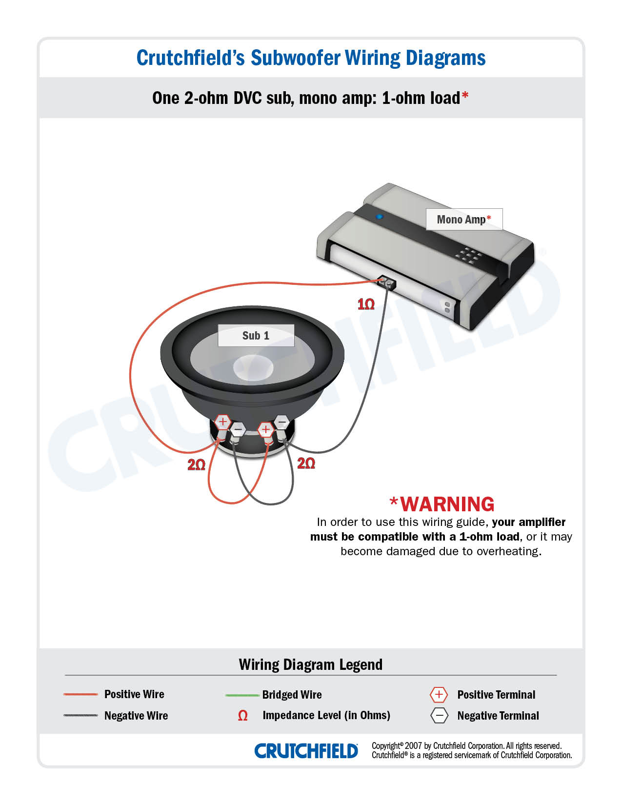
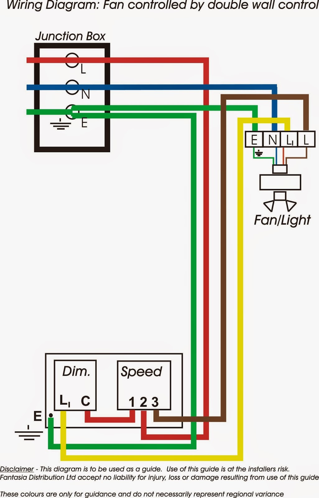
The following diagrams are the most popular wiring configurations. For top mounted battery posts the most common way to do this is to crimp a ring terminal onto the end of the.

Surfactin Production In Dac Ddisa And Pde Dgdpp And Dpgph
Mutant amp wiring diagram. Car radio wire diagram stereo wiring diagram gm radio wiring diagram. These directions assume you have already physically mounted your amplifier to a solid non conductive surface non metal. Hyundai car radio stereo audio wiring diagram autoradio connector wire installation schematic schema esquema de conexiones stecker konektor connecteur cable shema car stereo harness wire speaker pinout connectors power how to install. Mutant mt200 amp wiring need some help with a short how to on wiring up the following so i get the most out of itmutant mt2004 4 channel power ampintergrated high lowpass filters 12db 0ct4 x 50w rms at 4 ohms stereo4 x 70w rms at 2 ohms stereo2 x 140 rms at 4 ohms bridgedspeakers2 x tsa6910. Hyundai car radio wiring diagrams. Mustang vacuum routing diagram.
Zach wire each sub to its amp like this diagram. Here we have chevrolet wiring diagrams and related pages. 87 93 fuse box diagram. Ignition control module diagram. 4 ohm mono is equivalent to 2 ohm stereo. Figure a figure b 1965 chevy ii wiring diagram.
57 chevy 150 210 belair wiring diagram drawing a 1964 chevelle wiring diagram. Step 5 connect the power wire. These receptacles are usually found in kitchen wall outlets where two branch circuits are needed to serve small appliances and a refrigerator separately. 87 93 radio wiring diagram. Figure a figure b 1967 chevy ac assembly manual drawing a 1968 camero wiring in a pdf file. Diff rear end torque specs.
The rest of your system should resemble this amplifier wiring diagram with your second battery essentially taking the place of the diagrams capacitor. Wiring diagram for a 20 amp 120 volt duplex receptacle a 20 amp 120v duplex receptacle outlet like this should be installed in a circuit using 12 awg cable and a 20 amp circuit breaker. Guitar signal shown in pink enters the tube on the left at ac signal in the guitar signal flows through the grid stopper resistor to the tubes grid then out the tubes plate through the coupling capacitor and on to the next amp circuit. If you have not purchased your power wiring be sure to read this article on choosing wire gauge for amplifiers. Because those amplifiers have line level outputs you can daisy chain their connections to get inputs. Airbag diagnostic code clear.
They show a typical single channel wiring scheme. Check out our amplifier wiring diagram to see how the wiring gets connected in a typical 2 amp system. Figure a figure b 1965 impalla wiring diagram. Standard vacuum tube preamp stage. Belt routing smog pumpac removed. There is also a wiring diagram below.
Attach the power cable to the positive battery terminal not directly to the battery post itself. Single voice coil wiring options. Check the amplifiers owners manual for minimum impedance the amplifier will handle before hooking up the speakers.
