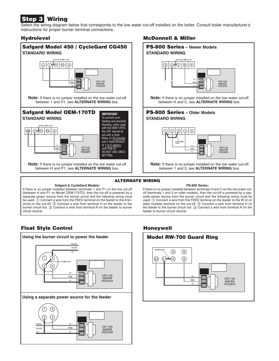
Dotted black lines indicate internal wiring. Connect wire from terminal hof water feeder to terminal h on lwco.

Sears 14 6 Lawnmower Repair Manual Manuals And Guides 4u
Mcdonnell miller ps 802 24 wiring diagram. Bold lines indicate action to be taken in step shown. Connect wire from terminal h of water feeder to terminal 1 on lwco. 148 basic wiring b asic w iring rb 24 12024vac transformer. Safgard 24 series lwco installation manual. Safgard ez plug wire harness installation manual. Hydrostat 3200 plus installation sheet spanish translation vxt feed valve service kit instructions.
Hydrostat pipe mounting kit instructions. Mcdonnell miller 153917 ps 802 24 electronic 24v low water cut off steam low water cut off electronic for steam boilers series ps 800 features for residential and commercial applications electronic operation user friendly diagnostics red low water and shorted probe led green power and test led higher probe sensitivity. Switches and how to wire popular mcdonnell miller products. Insert the stripped end of the wire under the wire clamping plate p and securely tighten the terminal screw n. Ps 802 24 24v using harness 7 ps 802 24 24v using harness 7. Dotted black lines indicate internal wiring.
Note that the control requires a. Grey lines indicate existing wiring. Basic wiring mcdonnell miller lwco water feeder wiring series ps 801802 lwco wf uni match series ps 801 120v with 24v burner circuit 24 and 120v series ps 800 controls 24 and 120v feeder 24v burner 120v feeder 24v burner 24v feeder series ps 802 24 series ps 801 120 older models 120v or 24v lwco with terminals 1 5 wwo p probe. They provide a positive and economical way to detect change or loss of air flow velocity caused by closed damper or fan inlet a loose fan wheel a slipped or broken fan belt a dirty or clogged filter or an overload on a fan motor switch. Bold lines indicate action to be taken in step shown. Mcdonnell miller installation maintenance instructions mm 216j green power on red low water 2.
The wiring diagrams show connecting the rb 24 on typical burner circuits. Diagram 1 wfe 24 ps 802 lwco wn h ps 801 120 lwco uni match water feeder wfe 120 field or factory jumper wire p1 23 45 connect wire from terminal n of water feeder to terminal 2 on lwco. Wiring diagram legends 1. Bold lines indicate action to be taken in step shown. 1 table of contents ps 800 series 5 pse 800 series 5 4242a and 18 42s42s a 93193 20 94194 22 150157 150s157s 24 1575 29 157s rbp 28 replacement probes. Wiring diagram legends 1.
Wwo p probe wire connection series ps 802 24. Connect wire from terminal w of water feeder to terminal 4 on lwco. Ps 801851 with 120 volt burner circuit with red low water and amber test lights. Wiring diagram legends 1. Ps 802 24 lwco bnh uni match water feeder wfe 24 factory jumper bar wnh connect wire from terminal nof water feeder to terminal n onlwco. Mcdonnell miller air flow switches sense air flow or no air flow by responding only to velocity of air movement.
Gallery of Mcdonnell Miller Ps 802 24 Wiring Diagram