It reveals the components of the circuit as streamlined shapes and also the power and signal connections between the devices. Connect wiring as shown in the wiring diagrams.
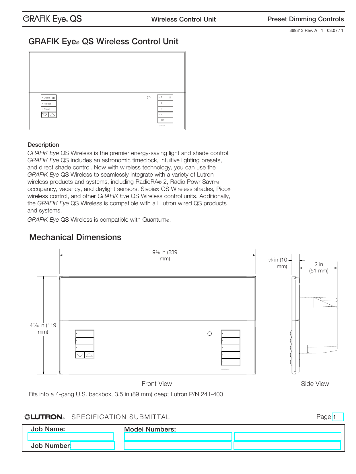
Grafik Eye Qs Wireless Control Unit Mechanical Dimensions
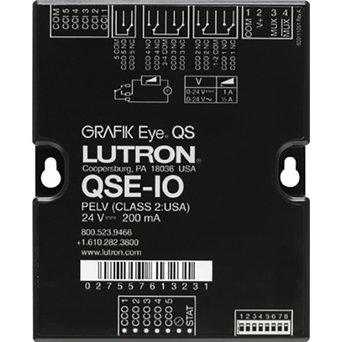
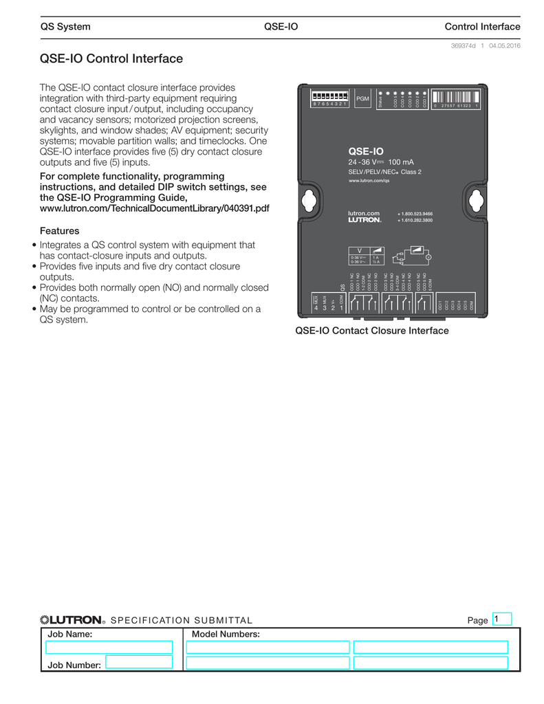
Lutron qse io wiring diagram. Each terminal accepts up to two 18 awg 10 mm2 wires. Qs system qse io control interface 369374d 7 02022018 wiring application examples 1 lutronr occupancy sensor wired to 1 qse io device input qse io terminals occupancy sensor wiring diagram is not applicable to. A wiring diagram is a simplified traditional pictorial representation of an electrical circuit. Consult grafik eye qs control unit specification submittal for more details. Qse io control interface. 500r 1000r or 2000r models power pack use model that corresponds to input voltage hot neutral red 20 to 24 v blue signal.
Strip 38 in 10 mm of insulation from wires. Usa qs link using the mux terminal 3 on the front of the unit. Each terminal accepts up to two 10 mm2 18 awg wires. Qse io 6 100609 qse io control interfaces wire the qse io interface to the pelv class 2. Total length of wire on a qs link must not exceed. Wiring may be daisy chain star or t tap configuation.
Low voltage pelv class 2. Assortment of lutron wiring diagram. Each data link terminal will accept up to two 18 awg 10 mm2 wires. Page 7 qs system qse io control interface 369374a 7 080712 wiring application examples multiple lutron occupancy sensors wired to multiple qse io device inputs 120 277 347 v 60 hz 230 v 50 60 hz neutral black red 20 24 v white blue signal black common power pack occupancy sensors 120 277 347 v 60 hz 230 v 50 60 hz neutral. Use lutron cable grx cbl 46l wiring notes 1. The status led blinks once per second when properly connected.
Gallery of Lutron Qse Io Wiring Diagram