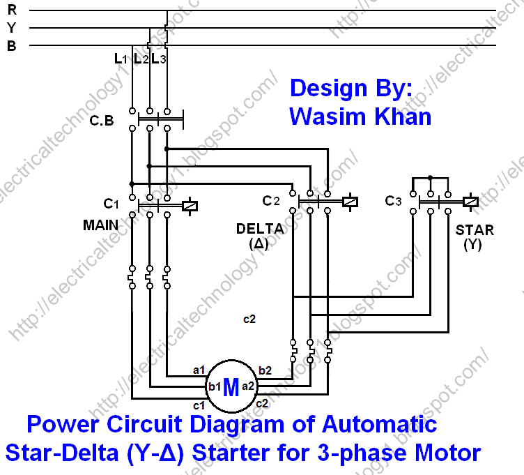
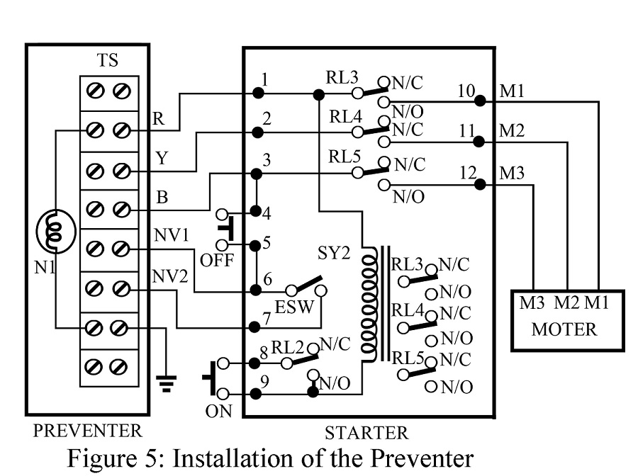
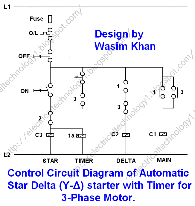
6 7 key diagram mk1 dol mb1 mb2 mu1 mu2 dol starter stop. Connect all three poles of relay in series as shown in the following diagram.

L Amp T Pdf Document
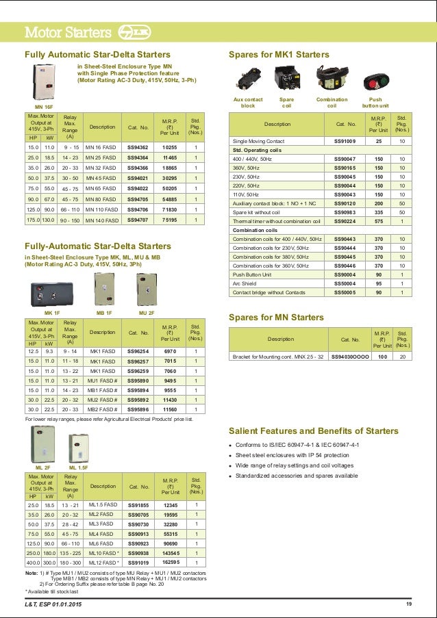
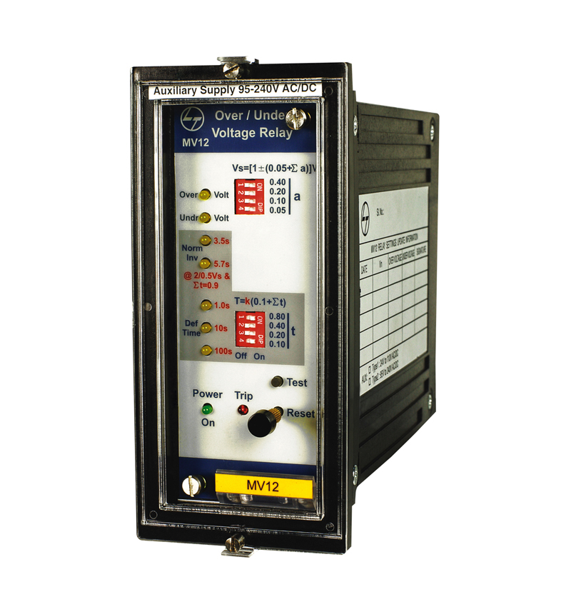
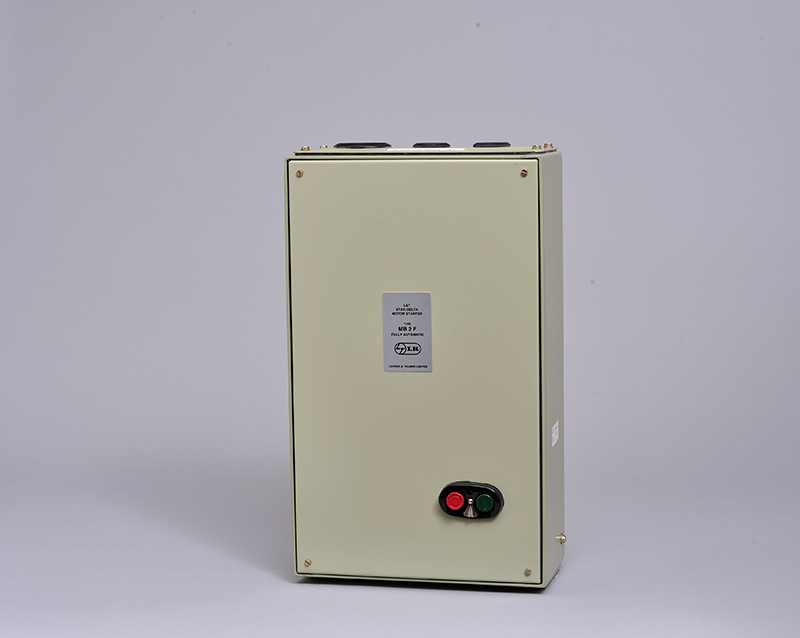
L t sdz5 wiring diagram. We have electrical products for all type of industrial usage. Lt sdz5 single phase preventor relay 380v ac for mu g15 mu g20 20h mu g30 mu g50 mu g76 controllers list price 122500 sale price 120222. Safe sure 30 lt switchgear esp service manual overload test 1m 1m dut 1m 1m. Lt offers two variants of fasd called starters and controllers. Fasd starters are basic electrical starters with contactor and relay combination for on off operation and overload protection of the pump sets. All you need the operating voltage the motor rating the various short circuit ratings and coordination types.
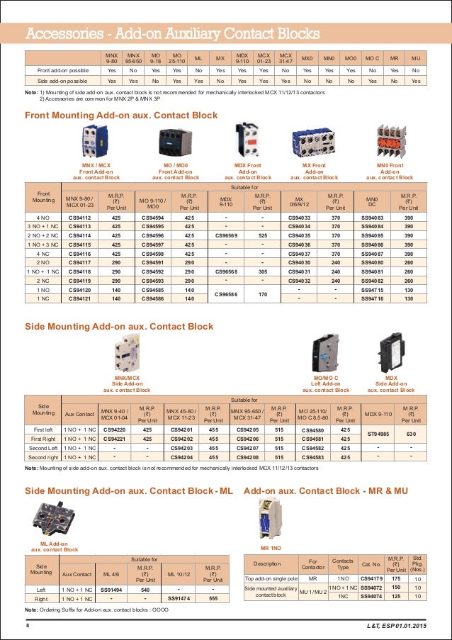
Unit h huntley il 60142 usa. Moeller wiring manual 0208 8 3 all about motors 8 motor protection selection aids the moeller selector slide enables you to determine quickly and reliably which motor starter is your most suit able for the application. Length of cable should be one metre. Shop cs96129oooo lt m starters wiring harness mu g20 sdz5 sppr online at wholesale prices. For price list call shopelect. For phase to neutral pilot supply disconnect 1 li a1 connect a1 to neutral.
Connect normally closed nc contact of relay in series with test panels auxiliary. Basic wiring for motor control technical data. For phase to phase pilot supply follow the wiring diagram exactly. Wiring diagram book a1 15 b1 b2 16 18 b3 a2 b1 b3 15 supply voltage 16 18 l m h 2 levels b2 l1 f u 1 460 v f u 2 l2 l3 gnd h1 h3 h2 h4 f u 3 x1a f u 4 f u 5 x2a r power on optional x1 x2115 v 230 v h1 h3 h2 h4 optional connection electrostatically shielded transformer f u 6 off on m l1 l2 1 2 stop ol m start 3 start start fiber optic. Use proper size of cables. For external pilot supply disconnect wires 1 l1 a1 13 5 l3 and connect external pilot supply to a1 94.
Reverse phase elv wiring diagram line voltage 120v 120v output led load low voltage dc powered by ltf ltf llc. Wiring diagrams sometimes called main or construction diagrams show the actual connection points for the wires to the components and terminals of the controller. 11966 oak creek pkwy. Wiring diagrams show the connections to the controller.
Gallery of L T Sdz5 Wiring Diagram