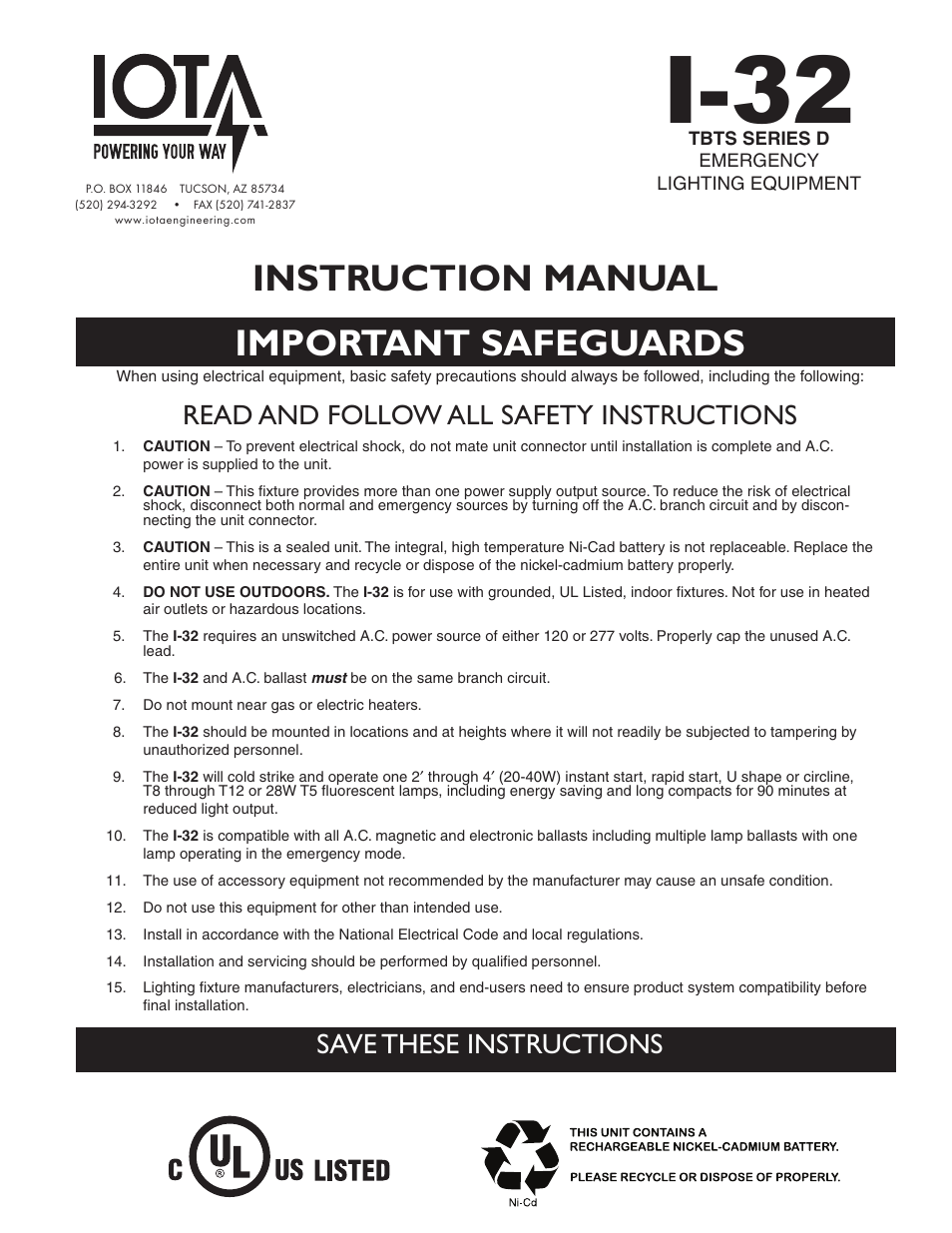
Input to the i 32 must be connected ahead of the fixture switch. The i 32 fluorescent emergency ballast from iota engineering allows the same fixture to be used for both normal and emergency operation.
I 320 Instruction Manual
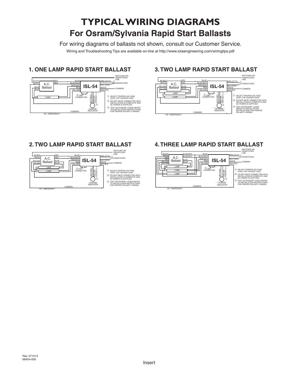
Iota i 32 wiring diagram. Iota resource for i 320 information specification sheets instruction manuals wiring diagrams and more 1 lamp 1350 lumens. If a lamp type is not listed the diagram shows a. If you cannot find a diagram that matches your particular application contact customer service or call 1 800 866 iota with details regarding your application. See the led. The i 320 he from iota engineering is a ul listed emergency ballast that allows the same fixture to be used for both normal and emergency operation. The diagrams are categorized primarily according to the number of lamps in the fixture then followed by the ballast type.
Wiring notes general wiring and troubleshooting tips can be found here. Select the proper voltage lead and cap the unused lead. Two lamp rapid start ballast 3. 4 light rapid start ballast wiring diagram 4 bulb ballast wiring diagram a wiring diagram is a streamlined standard photographic representation of an electric circuit. If a diagram cannot be found within this selection consult customer service. Most 2 4 single bipin t8 thru t12 ho and vho fluorescent lamps in parallel.
One lamp rapid start ballast 2. Iota i 32 wiring diagram 24102018 24102018 4 comments on iota i 32 wiring diagram the i from iota engineering is a ul listed fluorescent emergency ballast that allows the same fixture to be used for both normal and emergency operation. Iota resource for i 232 information specification sheets instruction manuals wiring diagrams and more 2 lamp 1400 lumens lamps 700 lumens per lamp. The i 32 requires an unswitched ac. Wiring diagrams select an available diagram from the list below. Most 2 4 single bipin t8 fluorescent lamps and 2 4 14w to 54w t5 ho and vho fluorescent lamps for use with select led retrofit tube lamps.
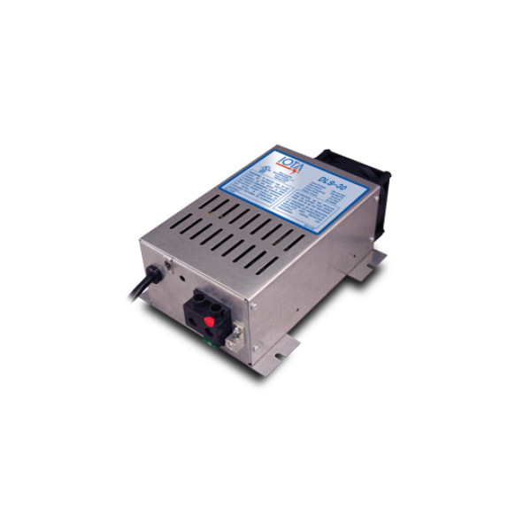
Two lamp rapid start ballast 4. The i 32 can be used with most 2 4 t8 thru t12 and. In the event of a power failure the i 32 switches to the emergency mode and operates one of the existing lamps for 90 minutes. When the i 32 is used with a switched fixture the ac. Refer to ac input wiring on illustration 3 of installation manual. In the event of a power failure the i 320 he switches to the emergency mode and operates one of the existing lamps for 90 minutesthe unit contains a battery charger and inverter circuit in a single can and can be mounted in the wireway or on.
The unit contains a battery charger and inverter circuit in a single can. Refer to illustration 3 for switched and unswitched fixture wiring diagrams. Typical wiring diagrams for wiring diagrams of ballasts not shown consult our customer service. Sometimes a specific lamp type is listed ie. 5 use either whtblk lead for wiring the common. Typical wiring diagram 4 lamp ballast books of wiring diagram iota i32 emergency ballast wiring diagram 41 wiring.
Power source of either 120 or 277 volts.
Gallery of Iota I 32 Wiring Diagram