A wiring diagram is a simplified traditional pictorial representation of an electric circuit. All wiring however must comply with local electrical codes.

How The Electronic Fan Control Works Youtube
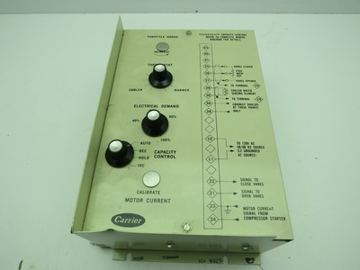
Heatcraft ftc5 eh01 wiring diagram. See wiring diagram two of these leads are for connecting the outdoor temperature sensor. On heatcraft quick response controller systemsthe main power for the evaporator is supplied separately from the power supply of the condensing unit. Most parts ship same day. High voltage there may be high voltage on. Properly connected according to the wiring diagram. Unit to the evaporator.
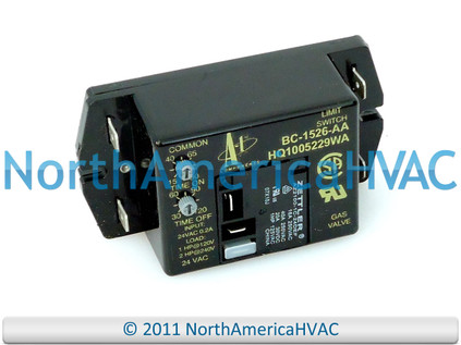
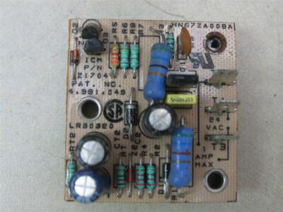
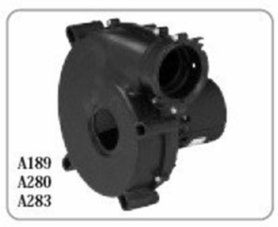
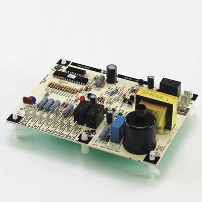
Warranty statement seller warrants to its direct purchasers that products including service. Icp heil tempstar comfortmaker icp heil tempstar fan relay control board bc1526aa bc7058ho ftc5eh01 st9000c1008. Heatcraft circuit board 28910101. Assortment of heatcraft walk in freezer wiring diagram. F all equipment is installed in accordance. Order from heritage parts the leading online provider of oem commercial kitchen replacement parts.
Installation wiring wiring at the unit coolers will be as follows see wiring diagrams. Low voltage wiring must be 18 gauge minimum. All 24 volt wiring must be run separate from the line voltage wiring. The other three leads are for connecting the compressor contactor service switch and 2v common inputs. To your heatcraft refrigeration products sales representative. It shows the elements of the circuit as simplified shapes as well as the power and signal links in between the gadgets.
E the factory installed wiring must not be changed without written factory approval.
Gallery of Heatcraft Ftc5 Eh01 Wiring Diagram
%2C445%2C291%2C400%2C400%2Carial%2C12%2C4%2C0%2C0%2C5_SCLZZZZZZZ_.jpg)