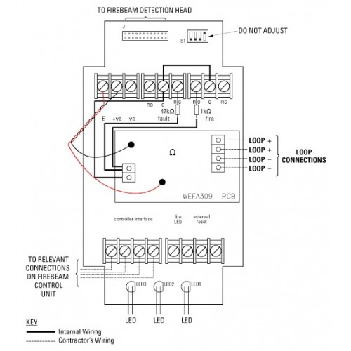
The cables connecting with remote led should be different colors to distinguish the polarity. The d1d2 is for 24vdc power supply.

Tv 1439 Beam Detector Wiring Diagram Free Diagram
Gst beam detector wiring diagram. Wiring twisted pair for detector two bus with cross section not less than 10mm. The beamsmk allows system sensor reflected beam detectors to be mounted when surface wiring is used. Parts diagram not to scale. Gst 5000 fire alarm panel gst addressable smoke detector wiring diagram. Alarm led does not light even when beams are blocked. Beam detector i 9105r mounting the detector the intelligent beam detector should be installed in compliance with all local codes having a jurisdiction in your area or nfpa 72 national fire alarm code nfpa 70 national electrical code bs 5389 and en54.
I 9102 intelligent photoelectric smoke detector installation and operation manual the intelligent solution mounting hole fig. The k11k12 for fire alarm output contact passive. Diagram illustrates correct placement of photo beams in relation to the gate. This is the basic fire alarm system used in household wiring. The detector can be mounted in 2 ways. According to the wire diagram.
A smoke or heat detector can be installed to the existing or new home wiring. The minimum size gauge 10mm² selection of compatible control panels compatible with all gst intelligent fire alarm panels gst 200 gst 5000 gst. Programming of i2c protocol devices like reflective beam detector and gst8903 mimic panel interrogates device for condition manufacturing batch number date of manufacture alarm sensitivity re program facility enables adjustment to alarm threshold of detectors. Beams reflect to the receiver. The cable must be fire rated and the size depends on the distance and application. Projected beam smoke detector 3825 ohio avenue st.
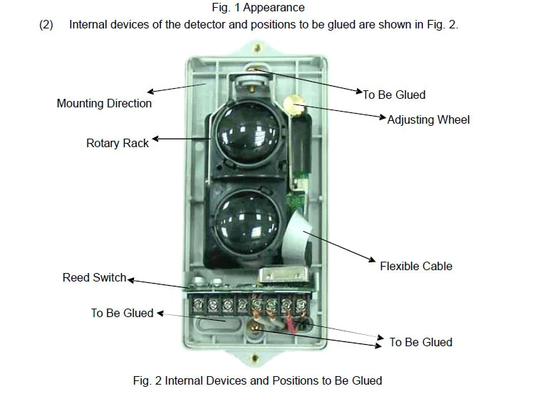
Unit mounting screw cover mounting screw wiring entrance see 6wiring for details ⑥align the beam and check the operation. The gto access systems photoelectric dual beam detector uses dual beam and through beam technology. Central battery system testing and commissioning fire alarm control panel edwords fi. Terminal block paintable trim ring c1049 00. This kit must be used when mounting the trans. Charles illinois 60174 800736 7672 fax.
Between zone wiring there is a resistor value 22k we call it eol resistor it provides the protection for the wiring also its a must to wire this in the sensor end default is on alarm panel. In our basic wiring diagram a single or multiple heat and smoke detectors are installed in the home by connecting the live line or hot neutral ground and an interconnected wire to the alarm. Connect wires to the terminals. ④ route wiring through the wiring entrance of the chassis and through the wiring entrance of the unit. Ir beam sensors get the power from alarm panel aux gnd and ir beam dry contact output connect to tamper and zone 1 in series. The installed onto standard two gang electrical.
⑤ hang the chassis and tighten the unit mounting screw to the chassis. Check the power supply and wiring.
Gallery of Gst Beam Detector Wiring Diagram