For model ddec ii 2 mode use the wiring diagram for. While the head light is connected wiggle your wiring harness all the way back to the either the batteries or the starter depending on where it gets its power from.
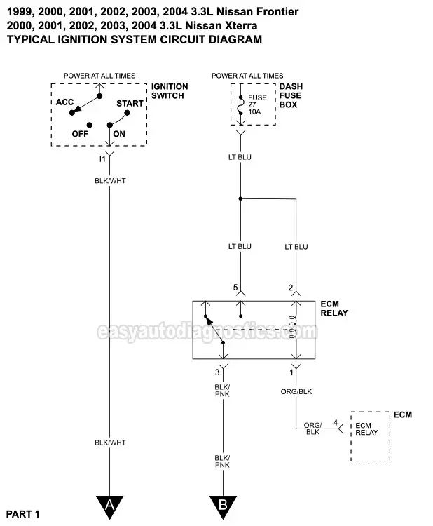
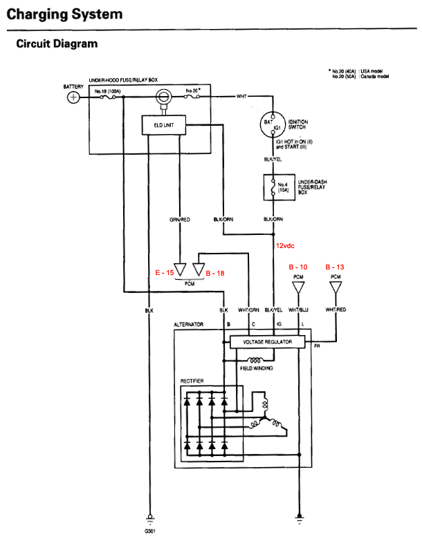
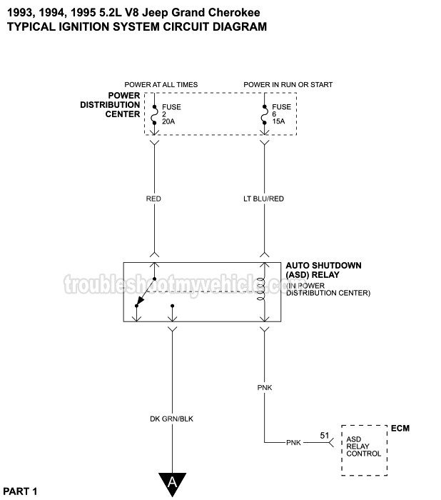
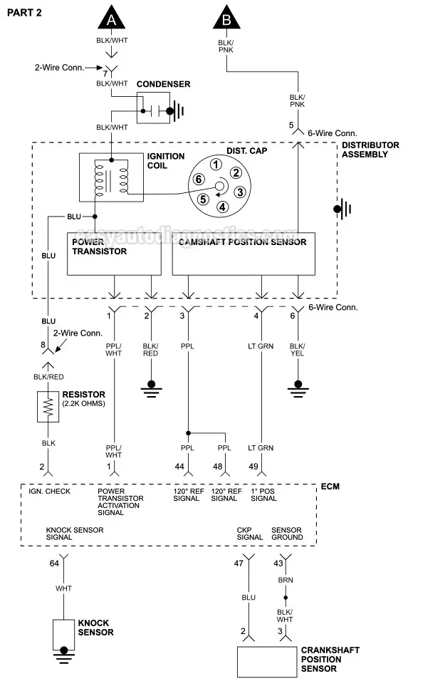
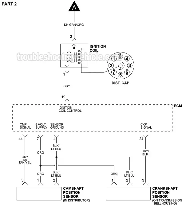
Part 1 Ignition System Wiring Diagram 1999 2004 3 3l
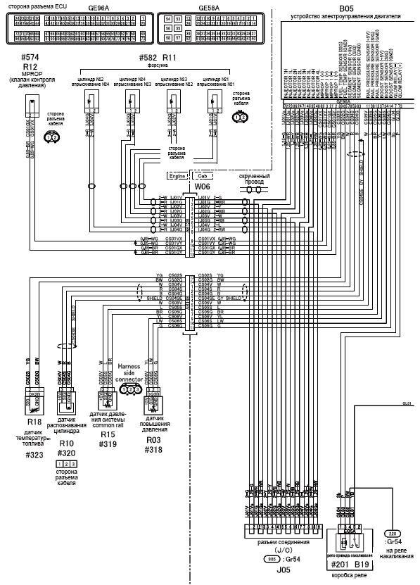
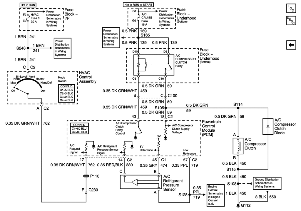
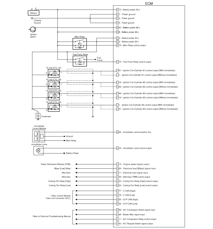
Ecm circuit wiring diagram. If the wiring has a bad spot the headlight will flicker or drop out. Todays can or controller area network communication arrays are difficult and complex and so is its diagnostic. Learn to test these larger units here with wiring diagram interpretation in mind. That bad connection cannot support an electrical load that is why you get weird ecm problems like this. It shows the parts of the circuit as simplified shapes and also the power and also signal connections in between the tools. A wiring diagram is a streamlined conventional photographic depiction of an electric circuit.
The ecm has isolator mounts for both vibration and electrical isolation. Hi all i have a cummins 24 valve isb 12 volt and could do with some does anyone have a wiring diagram of the ecm plug showing the. Ecm terminal and inputoutput signal. Pcm ecm wiring diagrams aprox kb per file sent by chris winn aka isb cummins for non ram applications. March 21 2019 by larry a. The ddec ii ecm is packaged in a.
Second generation xm 2011 2020 kia sorento xm 2011 2020 service manual engine control fuel system engine control system engine control module ecm circuit diagram. Assortment of cummins m11 ecm wiring diagram. Depending upon application some units schematic diagram of ddec ii. If atec is used connect this wire to atec ecm. Left half right half. Cummins isb cummins isl cummins b cummins l9 engine brake and ecm.
Engine control module ecm circuit diagram. Wire cut off black wire and insulate end.
Gallery of Ecm Circuit Wiring Diagram