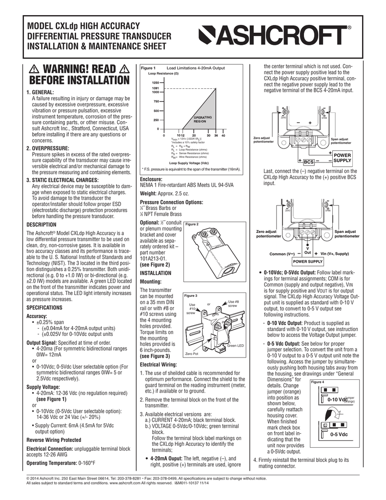
Pressure spikes in excess of the rated over p resuc abil t yofh nd m cause irreversible electrical andor mechanical damage to the pressure measuring and con taining. January 23 2019 by larry a.

Db87 Wiring Diagram For Pressure Transducer Wiring Library
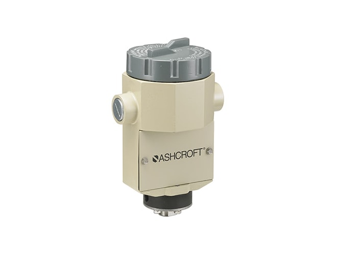
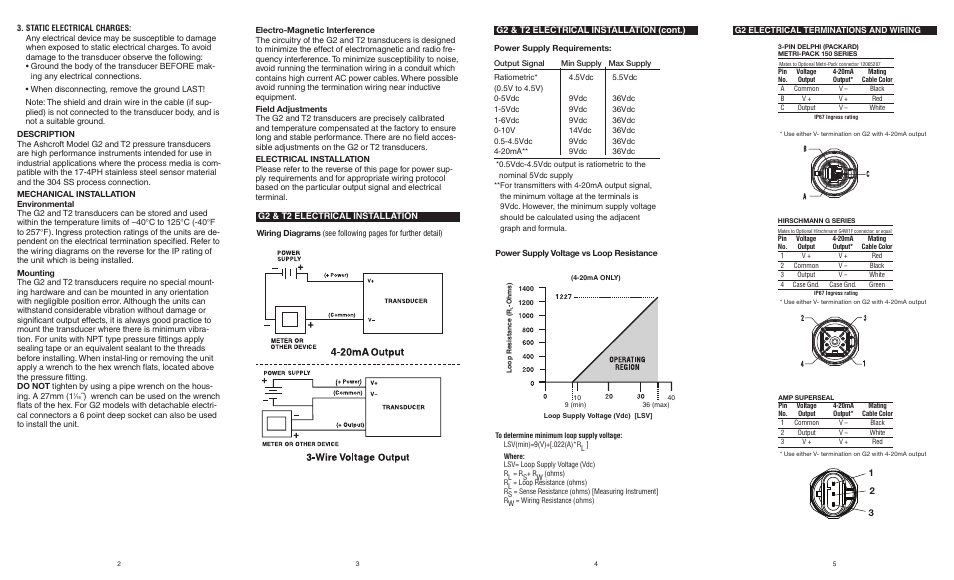
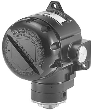
Ashcroft pressure transducer wiring diagram. Pressure transducer output remains constant re gardless of pressure. Consult ashcroft inc stratford connecticut usa before installing if there are any questions or concerns. Mounting the g2 g3 and t2 transducers require no special. Pressure transducer exhibits an output at zero pressure large zero offset. A wiring diagram is a streamlined standard photographic depiction of an electric circuit. The ashcroft model g2 g3 and t2 pressure transduc.
It shows the components of the circuit as simplified shapes and the power as well as signal connections between the devices. By headcontrolsystem ashcroft pressure transducer wiring diagram exactly whats wiring diagram. The wiring diagrams on the reverse for the ip rating of the unit which is being installed. Refer to the wiring diagrams on the reverse for the ip rating of the unit which is being installed. The ashcroft model g2 and t2 pressure transducers are high performance instruments intended for use in. Wellborn collection of ashcroft pressure transducer wiring diagram.
A wiring diagram is a kind of schematic which utilizes abstract pictorial signs to show all the affiliations of components in a system. Of the pressure containing parts or other misuse. Send by email email links for the selected installation maintenance manuals to.
Gallery of Ashcroft Pressure Transducer Wiring Diagram