Articles 501 502 503 andor cec. Collection of 1761 cbl pm02 wiring diagram.
1761 Cbl Pm02 Allen Bradley Plc Programming Cable For Ab
1761 cbl pm02 wiring diagram. Section 18 1j2 as appropriate. Page 4 18 removed catalog 1761 net dni chapter 4 added 1764 mm3 and 1764 mm3rtc to catalog table and new footnote. Page a 3 added relay output life to. 1761 cbl pm02 series c 1761 cbl hm02 series c 1761 cbl am00 series c 1761 cbl ap00 series c 2707 nc8 series b 2707 nc9 series b. A wiring diagram is a simplified traditional pictorial depiction of an electric circuit. This cable has a straight connector on the 8 pin round end.
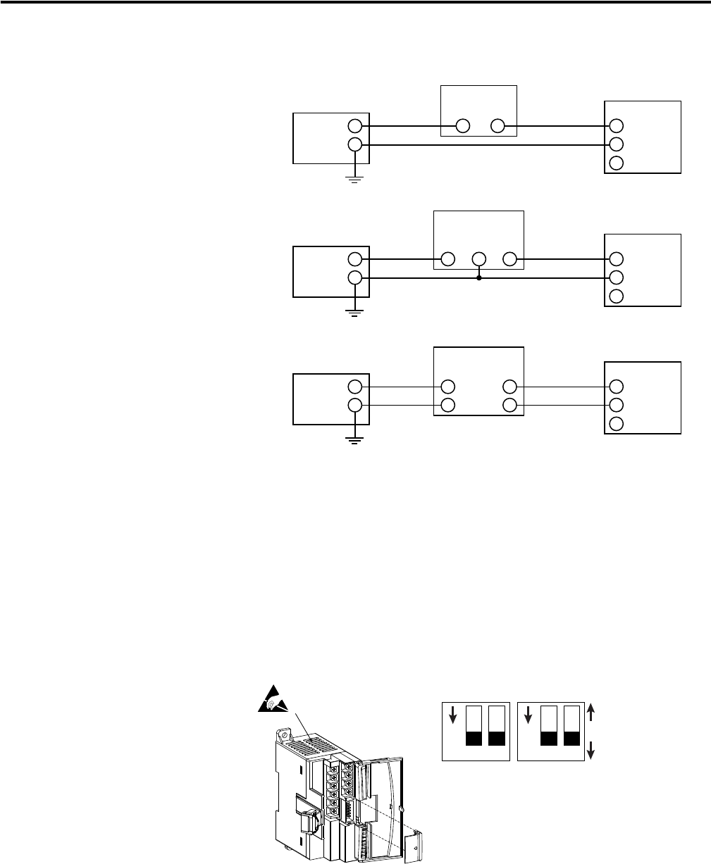
1761 cbl pm02 pinout 1761 cbl pm02 wiring diagram pm02 cable pin configuration post navigation previous wind speed sensor anemometer three cups aluminium current voltage output 0 5v. It shows the parts of the circuit as simplified shapes as well as the power and also signal links between the gadgets. We recommend that you locate the suppression device as close as possible to the load device. Communication cables for class 1 div environments environment classification communication cables class i division 2 hazardous environment 1761 cbl pm02 series c or later 1761 cbl hm02 series c or later 1761 cbl am00 series c or later. All wiring must comply with nec. Updated wiring diagram for 1761 cbl pm02.
1761 cbl pm02 wiring diagram sample collection of 1761 cbl pm02 wiring diagram. This db9 to round mini din 8 rs232 is a direct replacement for the allen bradley 1761 cbl pm02 micrologix plc programming cable. Radiating into system wiring and facility. The following diagram shows an output with a suppression device. Weve got allen bradley 1761 cbl ac00 cable connection micrologix to pc 9 pin d shell 9 pin d shell at wholesale prices at rexel usa register now. Page 6 1 added 1764 mm3rtc to footnote for table a1 general specifications page a 2 updated operating frequency for 1764 24bwa and 1764 28bxb.
4 16 communication connections 1761 cbl pm02 series c or equivalent cable wiring diagram programming controller device 9 pin d shell 8 pin mini din recommended user supplied components these components can be purchased from your local electronics supplier. A wiring diagram is a streamlined conventional pictorial depiction of an electric circuit. This 10 long serial cable fully supports rslogix 500 and rslinx communications df1 or dh 485. It shows the parts of the circuit as simplified shapes and the power as well as signal connections between the devices.
Gallery of 1761 Cbl Pm02 Wiring Diagram